HW 7 VGA Discs
Objective
In this project students will explicitly implement a computational finite-state machine, utilize manual rescheduling to distribute multiplications, and resource sharing. Students will become familiar with the concept of using and use an on-chip clock manager. Students will utilize the faster clock to implement computations in a serial fashion. In this HW students will display a discs onscreen, examine timing analysis and utilization reports, and modify synthesis options.
Due Dates
- Due Tuesday May 14 (last day of class)
Description

1. Start with a working VGA display project
- integrate the simple VGA sync module designed to work with a 50 MHz input clock
- you should use or implement HW1 in Verilog a starting point (no schematics)
2. Build a design with Generated Clocks with New Frequencies using a Clocking Wizard
-
Modify the XDF file so that the create_clock line is as follows ( the previous version added a redundant name in the second command that muddies clock analysis reports)
set_property -dict { PACKAGE_PIN E3 IOSTANDARD LVCMOS33 } [get_ports { CLK100MHZ }]; #IO_L12P_T1_MRCC_35 Sch=clk100mhz create_clock -period 10.00 -waveform {0 5} [get_ports {CLK100MHZ}]; -
Add a Clock Manager Xilinx IP to your VGA Rectangle top design to to generate a 150 MHz Clock for faster core pixel drawing computations and a 50MHz clock for the VGA sync module
-
As you’ve learned before, start to generate an IP Core using the IP Catalog
-
Options to modify in the Clocking Wizard
- Clocking Options Tab ->
- Input Clock Information -> Set Port Name for Input Clock “Primary” to clk_in_100M and make sure that Input Freqeency is 100MHz
- Likewise for Output Clocks Tab ->
- In the table enable two output clocks and set Requested Output Frequency to 150 MHz and 50 MHz
- set appropriate Port Names to clk_out_150M and clk_out_50M
- Clocking Options Tab ->
-
Accept the defaults otherwise and process to generating your core
-
The generated module should look something like this:
module clk_wiz_0 ( // Clock out ports output clk_out_50M, output clk_out_150M, // Status and control signals input reset, output locked, //(this is an output that indicates with the clock outputs are stable) // Clock in ports input clk_in_100M ); -
Modify your design so that
vga_rectangleuses the 150 MHz clock- the
vga_syncmodule uses the 50MHz clock - the original 100 MHz system clock is provided as the input of the Clock Manager
- CAREFULLY CHOOSE NAMES FOR THE GENERATED CLOCK NETS AT THE TOP LEVEL VERILOG SO THAT YOU CAN DISTINCTLY IDENTIFY THEM IN REPORTS
-
Add a reset signal to your system and provide it to the Clock Manager (note in simulation that the Clock Manager may expects the reset to be asserted for multiple clock cycles, so check documentation)
-
Complete Implementation and Bitstream Generation and Verify that your design shows a rectangle on a VGA display
-
Verify that multple clocks reported from the TCL console command “report_clocks”
-
Timing Report:
Now, generate a timing report
run the following command in the TCL console:
to vivado main log:report_timing_summary -delay_type min_max -report_unconstrained -check_timing_verbose -max_paths 10 -input_pins -routable_nets -name timing_1```to file:
report_timing_summary -delay_type min_max -report_unconstrained -check_timing_verbose -max_paths 10 -input_pins -routable_nets -file timing_report.rpt-
In the file, find the “Clock Summary” section and include that section in your report for the following implemenations. Verify that there are additional clocks domains in your system. Also, see the sections “Intra Clock Table” and “Inter Clock Table” and include those in your report.
-
Now, look for the section “Design Timing Summary”
- Verify the presence of the following statement in the timing report: “All user specified timing constraints are met.”
- Report the Worst Negative Slack value (positive is good, negative is bad) for your implementations
-
-
Clock Interactions Report: Generate a specialize report using the following command in the TCL console
report_clock_interaction- Include this in your report for the implementations that follow
- Verify the all Inter-Clock Contraints are listed as “Clean”
-
Utilization Report: Now have a look at the utilization using the TCL command
report_utilization- then dump the same report to a file using the command “report_utilization utilization.rpt”
- though not used in this design, for the next designs submit what sections are required to document DSP48E1 utilization
DO NOT SUBMIT REPORTS FOR THIS DESIGN ITSELF. Submit the mentioned sections of clock, timing analysis, and utilizations for the following implemenations.
3. Implement Discs rather than a rectangle
A disc (filled cirle) of radius 100 at (xC,yC) can be implemented with the following function: (pixel_h_pos-xC)^2 + (pixel_v_pos-yC)^2 < 10000
Instead of drawing a rectangle, draw discs using this formula.
Modify the vga_rectangle to be vga_dics so that is has a case-statement-based computational state-machine that tests if a pixel is within a certain distance of three center points. Your state-machine should use the single-always-block style and must have the calculations embedded in the sate machine code (no separate datapath).
Requirement: there should be no more than one multiplcation per cycle so as to facilitate resource sharing. To assist resource sharing, decide a variable name that will have a multiplication result assigned to it every clock cycle. Propagate that result into a register in each cycle as appropriate.
Implement this vga_dics as a PARAMETERIZED module that can draw 3 filled discs.
Your module should be implemented with 6 redifinable parameters (use keyword parameter): 3 X-center, 3 Y-center, and 3 radii.
Demonstrate the following three discs by instantiating your module in the top.sv using parameter “override” in the instatation.
- (320,240+50) with radius 142;
- (320-80,240-80) with radius 25;
- (320+80,240-80) with radius 25;
Explore Resource Utilization and Resource Sharing
-
Once you have verified that your design works and shows the desired image in the screen continue by exploring resource utilization.
-
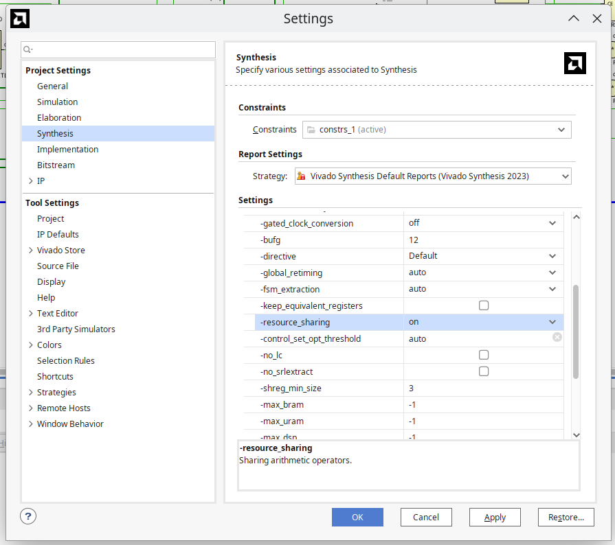
Toggle resource sharing explicitly on and off and generate two sets of utilization and timing reports.
-
Specifically, find how many DSP48E1 blocks are used in your design with and without resource sharing. Include the relavant parts of the utilization reports in your submitted report.
Submission
- In your report, be include requested information on clocks, timing slack, and utilization for your two implementations: “resource sharing on” and “resource sharing off”.
Appendix
blackboard post
The version of vga_sync found in the link posted in the HW 7 is this one: http://web.mit.edu/6.111/www/f2005/code/jtag2mem_6111/vga_sync.v.html
It is desiged to work with a 50 MHz input clock.
Some of you have been using a modified version to work with a 100 MHz input clock. You should revert to the version in the link posted this HW.
Modified for 100 MHz clk:
reg    [1:0] pcount;          // used to generate pixel clock
wire   en = (pcount == 0);
always @ (posedge clk) pcount <= pcount + 1;
Version in posted link designed for 50 MHz clock:
// pixel clock: 25Mhz = 40ns (clk/2)
reg 		pcount;		 // used to generate pixel clock
wire 	en = (pcount == 0);
always @ (posedge clk) pcount <= ~pcount;
assign 	pix_clk = en;