State Machine to Utilize Timer
Table of Contents
Typically students are exposed to the idea of designing a statemachine to perform a task, with the statemachine representing the system design. However, the more specific common practice is to design a statemachine to be integrated with selected pre-existing datapath components and I/O. For instance, rather than designing a statemachine to implement I/O patterns with timing specifications, a better exercise is to design a minimal statemachine to utilize a provided timer in a complete system design.
Assignment
Task: Using the timer module below and a state machine, program the FPGA with a design such that
if a button is pressed for 1 second
then an LED is then turned on for 2 seconds and then turned off
You need to know that the input clock has a frequency of 100 MHZ
You would be expected to submit
- your state machine diagram
- SystemVerilog code for the state machine (e.g.
fsm.sv) - a testbench for the state machine (e.g.
fsm_tb.sv) - top-level SystemVerilog (e.g.
top.sv) with instatiations of the fsm and timer - a testbench for
top.sv(e.g.top_tb.sv) - testing results as text and/or annotated waveforms
- report description
(not graded, just pushing you to complete)
Provided Material and Files
- Reference Manual: https://digilent.com/reference/programmable-logic/nexys-a7/reference-manual
- Relevant Section for I/O: https://digilent.com/reference/programmable-logic/nexys-a7/reference-manual#basic_io
- Provided xdc file: https://github.com/Digilent/digilent-xdc/blob/master/Nexys-A7-100T-Master.xdc
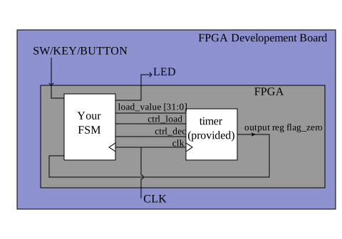
provided timer.v
// File: timer.v
module timer(output reg flag_zero, input [31:0] load_value, input ctrl_load, input ctrl_dec, input clk);

  reg [31:0] count,_count;
  reg        _flag_zero;

  always @ (posedge clk) begin
    count <= _count;
    flag_zero <= _flag_zero;
  end

  always @ (*) begin
    if (ctrl_load)
      _count = load_value;
    else if (ctrl_dec) begin
      if (count > 0)
        _count = count - 1;
      else
        _count = count;

      if (_count == 0)
         _flag_zero = 1;
      else
        _flag_zero = 0;
  end
end