Lecture 07 – Ch3 Ch4 Implementations Data Flow Implementation in Hardware and Software Analysis of Control and Data Flow
Ryan Robucci1. References
- \(\dagger\) A Practical Introduction to Hardware Software Codesign Patrick Shaumont
2. Mapping Dataflow to Software
- Choices for mapping dataflow to software:
- Parallel using multiple CPUs (Processor Networks)
- Sequential using a single CPU
- Dynamic Schedule: firing decisions at run-time, uses executive thread(s) to monitor queues and activate execution of actors based on firing rules at runtime
- Static Schedule:
- firing order can be decided at compile/synthesis time
- Therefore, can remove firing rule checking from run-time execution
- can map multiple actors firing to a deterministic sequential execution with multiple actors code combined as in-line code and optimized
3. FIFO Queues

- based on Figure 3.2 \(\dagger\)
- Software interface
- Queues characterized by 2 parameters:
- number of elements
- type of elements
- Provides three Methods (functions on the queues)
- put elements in queue
- get (and remove) elements from queue
- test number of elements in queue
- Queues characterized by 2 parameters:
- Book shows implementation of a FIFO as a circular buffer.
- Here is a variation to match the depiction and explanation that follows herein:
#include <assert.h>
#include <stdio.h>
#include <stdbool.h>

#define MAXFIFOSIZE 3

typedef struct fifo {
  int data [MAXFIFOSIZE]; // contiguous block of memory for token storage
  unsigned int writeOffset;   // write offset into contiguous block
  unsigned int readOffset;    // read pointer
  bool flagFull;
} fifo_t;


void init_fifo (fifo_t * F){
  F->writeOffset=0;
  F->readOffset=0;
  F->flagFull=false;
}

unsigned fifo_size(fifo_t *F) {
  unsigned size;
  if (F->writeOffset >= F->readOffset){
    size = F->writeOffset - F->readOffset;
  }else{
    size = F->writeOffset + MAXFIFOSIZE - F->readOffset;
  }
  if (size==0 && F->flagFull){
    size=MAXFIFOSIZE;
  }
  return size;
}

void put_fifo(fifo_t *F, int d) {
  if (!(F->flagFull)) {
    printf("Write %d\n",d);
    F->data[F->writeOffset]=d;
    F->writeOffset = ((F->writeOffset)+1) % MAXFIFOSIZE;
    F->flagFull = (F->writeOffset == F->readOffset);
    printf("New writeOffset: %d\n",F->writeOffset);
    printf("New flagFull: %d\n",F->flagFull);
  }else{
    printf("No Write, FIFO is already Full\n");
  }
}

int get_fifo(fifo_t *F) {
  int result;
  if (F->writeOffset!=F->readOffset || F->flagFull) {
    result = F->data[F->readOffset];
    F->readOffset = ((F->readOffset)+1) % MAXFIFOSIZE;
    F->flagFull = false;
    printf("New readOffset: %d\n",F->readOffset);
    printf("New flagFull: %d\n",F->flagFull);
  } else {
    result = -1;
  }
  return result;
}

void print_fifo(fifo_t *F){
  unsigned size = fifo_size(F);
  printf("FIFO size: %d :: ",size);
  printf("FIFO Contents: ");
  for (int index=0;index<size;++index){
    printf("%d ",F->data[(F->readOffset+index)%MAXFIFOSIZE]);
  }
  printf("\n");
}

int main() {
  fifo_t F1;
  int token;

  init_fifo(&F1);
  put_fifo(&F1, 3);                     // put 3
  print_fifo(&F1);
  put_fifo(&F1, 5);                     // put 5
  print_fifo(&F1);
  token = get_fifo(&F1);                // get 3
  printf("token:%d\n",token);
  put_fifo(&F1, 7);                     // put 7
  print_fifo(&F1);
  put_fifo(&F1, 11);                    // put 11
  print_fifo(&F1);
  put_fifo(&F1, 3);                     // put 12 fail (token lost, system result would be incorrect)
  print_fifo(&F1);
  token = get_fifo(&F1);                // get 5
  printf("token:%d\n",token);
  token = get_fifo(&F1);                // get 7
  printf("token:%d\n",token);
  token = get_fifo(&F1);                // get 11
  printf("token:%d\n",token);
  token = get_fifo(&F1);                // failed get
  printf("token:%d\n",token);
}
Write 3
New writeOffset: 1
New flagFull: 0
FIFO size: 1 :: FIFO Contents: 3
Write 5
New writeOffset: 2
New flagFull: 0
FIFO size: 2 :: FIFO Contents: 3 5
New readOffset: 1
New flagFull: 0
token:3
Write 7
New writeOffset: 0
New flagFull: 0
FIFO size: 2 :: FIFO Contents: 5 7
Write 11
New writeOffset: 1
New flagFull: 1
FIFO size: 3 :: FIFO Contents: 5 7 11
No Write, FIFO is already Full
FIFO size: 3 :: FIFO Contents: 5 7 11
New readOffset: 2
New flagFull: 0
token:5
New readOffset: 0
New flagFull: 0
token:7
New readOffset: 1
New flagFull: 0
token:11
token:-1
Depiction of Length-24 and Length-3 circular buffer
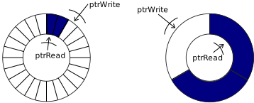
Example Length-3 Implementation:
- Initially empty array, with writePtr and readPtr at the same location
- Initially Empty

- Put: write 3

- Put: write 5
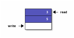
- Get: read returning 3
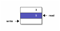
- Put: write 7
- writePtr wraps around to begining of allocated block

- Put: write 11
- writePtr becomes same as readPtr
- onset of Queue Full

- Get: returns 5

- Get: returns 7,
- readPtr pointer wraps around to begining of allocated block
- 1 element in queue
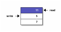
- Get: returns 11,
- readPtr becomes same as writePtr
- onset of Queue Empty

- In this depicted implementation, when the read pointer catches up with the write pointer, the array is empty.
- When the write pointer catches up with the read pointer the array is full.
- Options for encoding full and empty:
- Option 1 : flag bit: whenever, the read and write pointer become equal, a flag is used to record which state (full/empty) the queue is in
- Option 2 : extra bit in read an write addresses (explained later in this course): the full vs empty state is encoded by having the read and write pointers with an extra msb representing an inflated address range
- Option 3 : maintain an empty slot in the physical queue (used in book), so that the write pointer is never allowed to catch up with the read pointer. Full is flagged when the write pointer reaches the position proceeding the read position
4. Actors
- In software you can code actors several ways, but a function who's arguments are queues is sufficient.
- In the case of a dynamic scheduler, there should also be a table of rules provided or a function to determine the ability to fire the actor. (Could be embedded in the actor function – the code would check the firing condition and simply not perform any action when called)
Example max 8-out and max 8-in IO Descriptor for an Actor \(\dagger\)
#define MAXIO 8
typedef struct actorio {
  fifo_t *in[MAXIO];
  fifo_t *out[MAXIO];
}actorio_t;
Actor with in-built firing rule \(\dagger\)
void fft2(actorio_t *g){
   int a,b;
   //firing rule on next line
   if (fifo_size(g->in[0])>=2) {
     // pull data from queue(s)
     a = get_fifo(g->in[0]);
     b = get_fifo(g->in[0]);
     //compute and place output tokens
     put_fifo(g->out[0], a+b);
     put_fifo(g->out[1], a-b);
   }
}
- The conceptual advantage of an actor with an in-built firing rule is that it can be ignorantly yet safely called regardless of its need to fire or not. The caller does not need to first determine if the actor will fire or not.
5. Scheduler
A scheduler is the part of the software responsible for deciding the calls to actors and then performing the calls.
while(1){
  fft_actor (&fft_io)
   // .. call other actors
}
- A dynamic scheduler should have some ability to test firing conditions by checking the number of elements in the input queues. This requires some information about the firing rules of each actor.
- A static scheduler would just call the actors in a predetermined order.
- "3.1.3.1 Multi-threaded Dynamic Schedules" discusses extentions for
multi-threaded execution in case multi-processors are available
- when finished, actors yeild the processor to the scheduler to allow it to choose the next actor to invoke
6. Static Firing Schedule
- Find PASS firing vector, find PASS while adding initial tokens (values in queues) as needed
- Where choices arise, you can try to optimize storage by
- removing the firing decisions and
- in-lining the various actors' codes directly in the main body of code, we essentially have normal code.
- ideally queues may be single variables, thus not requiring a queue for implementation
7. Example
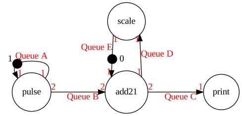
#define MAXIO 8
typedef struct actorio {
  fifo_t *in[MAXIO];
  fifo_t *out[MAXIO];
}actorio_t;
assume fifo_t is now float
Actors with in-built firing rule
void pulse_inbuiltfr(actorio_t *g){
   float x,r0,r1;
   if (fifo_size(g->in[0])>=1) { //firing rule
     // pull data from queue(s)
     x = get_fifo(g->in[0]);
     r0=x;
     r1=x;
     //compute and place output tokens
     put_fifo(g->out[0], r0);
     put_fifo(g->out[0], r1);
     put_fifo(g->out[1], 0);
   }
}

void add21_inbuiltfr(actorio_t *g){
   float x,y,z,r;

   if (fifo_size(g->in[0])>=2 && fifo_size(g->in[1])>=1) { //firing rule
     // pull data from queue(s)
     x = get_fifo(g->in[0]);
     y = get_fifo(g->in[0]);
     z = get_fifo(g->in[1]);
     //compute
     r = x+y+z;
     //place output tokens
     put_fifo(g->out[0], r);
     put_fifo(g->out[1], r);
     put_fifo(g->out[1], r);
   }
}

void scale_inbuiltfr(actorio_t *g){
   float x,r;

   if (fifo_size(g->in[0])>=1) { //firing rule
     // pull data from queue(s)
     x = get_fifo(g->in[0]);
     //compute
     r = x/2;
     //place output tokens
     put_fifo(g->out[0], r);
   }
}


void print_inbuiltfr(actorio_t *g){
   float x;

   if (fifo_size(g->in[0])>=1) { //firing rule
     // pull data from queue(s)
     x = get_fifo(g->in[0]);
     //act
     print("%f\n",x);
   }
}
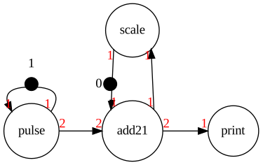
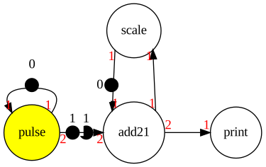
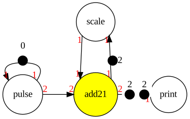
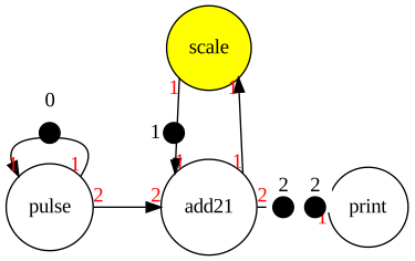
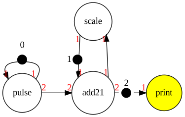
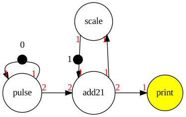
end of one PASS cycle start a new cycle
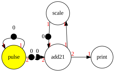
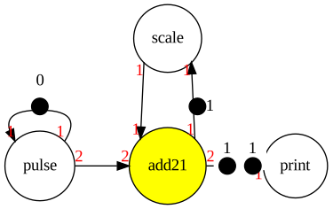
and so on…
output will be 2 2 1 1 0.5 0.5 …
A simple scheduler can be implemented if firing rules are in-built
while(1){
  pulse_inbuiltfr (&pulse_io)
  add21_inbuiltfr (&add21_io)
  scale_inbuiltfr (&scale_io)
  print_inbuiltfr(&print_io)
}
If inbuild firing rules are removed from each actor function, a dynamic schedule would need to perform a test before invoking each actor function. Assume actors, pulse add21 scale and out with no inbuilt firing rules:
while(1){
  if (/*firing rule for pulse satisfied*/)
     pulse (&pulse_io);
  if (/*firing rule for add21 satisfied*/)
     add21 (&add21_io);
  if (/*firing rule for scale satisfied*/)
     scale (&scale_io);
  if (/*firing rule for out satisfied*/)
    print(&print_io);
}
If a known valid firing pattern exists, the firing tests are not required Static Scheduler:
while(1){
  pulse (&pulse_io);
  add21 (&add21_io);
  scale (&scale_io);
  print(&print_io)
  print(&print_io)
}
Static and Inline not requiring firing rule tests anywhere:
while(1){

  //pulse (&pulse_io);
  x = get_fifo(A);
  put_fifo(B,x);
  put_fifo(B,x);

  //add21 (&add21_io);
  x = get_fifo(B);
  y = get_fifo(B);
  z = get_fifo(E);
  r=x+y+z;
  put_fifo(C,r);
  put_fifo(C,r);
  put_fifo(D,r);

  //scale (&scale_io);
  x = get_fifo(D);
  r = x/2;
  put_fifo(E,r);

  //print
  print("%f\n",get_fifo(C));

  //print
  print("%f\n",get_fifo(C));
}
Example of inline with FIFOs around scale actor reduced to variables.
while(1){
  //pulse (&pulse_io);
  x = get_fifo(A);
  put_fifo(B,x);
  put_fifo(B,x);
  //add21 (&add21_io);
  x = get_fifo(B);
  y = get_fifo(B);
  z = e;
  r=x+y+z;
  put_fifo(C,r);
  put_fifo(C,r);
  d = r;

  //scale (&scale_io);
  e = d/2;

  //print
  print("%f\n",get_fifo(C));
  //print
  print("%f\n",get_fifo(C));
}
Continuing along such lines, the entire program could be converted to inline code with fixed-length queues implemented as multiple variables, and desired initialization for initial token values would happen before the while loop.
8. HW Implementaion of Single-Rate Data Flow Graphs
- Book's mapping rules (assumptions):
- actors implemented as combinational circuits
- queues implemented as wires
- initial tokens become registers
- Therefore
- Actors implemented as combinational circuits will operate within a single clock cycle
- A chain of back-to-back actors without a register (initial token) between must operate as a whole in less than a clock cycle, their combinatorial delays add
- A critical path can be identified from the resource graph as the back-to-back actor chain with the largest sum of delays, which related to the maximum allowed clock speed
9. HW Implementation of C Code
- We'll now analyze a process for converting a limited subset of C code to combinational HW
- We'll first need to identify connections required in the hardware
10. Data and Control Edges of a C Program
- For the moment, view C as algorithm behavior description
- Data Edge
- defines data production and consumption relationship
- fundamental aspect of algorithm (information flow)
- must always be implemented
- Control Edge
- defines order of execution/firing (e.g. actor X must fire before actor Y)
- consequence of implementation
- not fundamental, may be removed in case of possible concurrency
11. Control and Data Flow Graph (CFG and DFG) Analysis of C Code
| Code | Operation | Consume | Produce | |
|---|---|---|---|---|
| 1: | int max(int a,b){ | enter | _ | a, b |
| int r; | _ | _ | _ | |
| 2: | if (a>b) | if then else | a,b | a flag known as (a>b) |
| 3: | r=a; | _ | a,(a>b) | r |
| else | _ | _ | _ | |
| 4: | r=b; | _ | b, (a>b) | r |
| 5: | return r; | return max | r | _ |


12. Constructing DFG and CFG
- C allows writing to variables multiple times before use making identification of data producer-consumer relationships difficult
- To construct the data flow graph, we'll use a control flow graph (CFG)
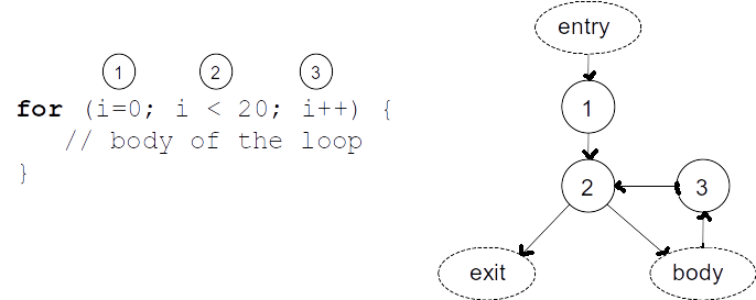
- A control path is identified according to conditional branching conventions in C
13. CFG for conditional branching
 †Shaumont
 †Shaumont
14. Constructing DFG
- Edges from Explicit Assignment Statements:
- Start by identifying a node \(\bf j\) which consumes a variable
\(\bf v\) .
- Identify all possible nodes \(\bf i\) which write to \(\bf v\) .
- Draw a line from \(\bf i\) to \(\bf j\) if a control path exist
from \(\bf i\) to \(\bf j\)
AND no node in that path also writes to \(\bf v\) - Repeat for every node \(\bf j\) and every variable \(\bf v\) it uses
- Start by identifying a node \(\bf j\) which consumes a variable
\(\bf v\) .
- Edges from Conditional Expression Evaluations (have implicit output flag variable)
- Add data edge from conditional expression evaluation node \(\bf i\) to \(\bf j\) if a control path exists from \(\bf i\) to \(\bf j\)
Example 1
1: int func(int a){
2:   a=a*2;
3:   a=a+1;
4:   return a;
   }
CFG:

DFG:
inital:

DFG after pruning using C.F.G.:
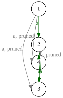
15. Example 2
1: int func(int a,int b){
2:   while (b>a){
3:     a=b;
4:     a=a*2;
     }
5:   return a;
   }
CFG:

DFG: examining only consumer node j=4 and only symbol a with all
potential producers
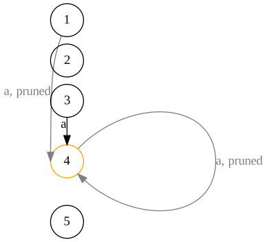
16. Example 3
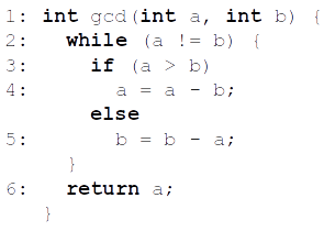 †Shaumont
 †Shaumont
 †Shaumont
 †Shaumont
17. A First Approach to Translate C to Hardware
- Assumptions for this approach of C to Hardware translation
- Only scaler code ( no pointers or arrays)
- Each C statement is a single clock cycle (will visit alternatives later)
18. Designing Data Paths
- C variables implemented in HW as registers w/multiplexer if multiple sources (mux controlled by FSM controller)
- C expressions implemented as Combinatorial Code, output results appropriately as either
- data for datapath (example where b is a register: "b=a+1;" The expression a+1 is in the data path )
- flags for controller (example: "if (a>b) b = a+1;" a>b is a generated flag fed to the controller)
- data path and register variables connected according to DFG
- for each assignment, connect combinatorial to register
- for each data edge, connect register to input of combinatorial circuit
- connect appropriate system inputs and outputs
Example: GCD
 †Shaumont
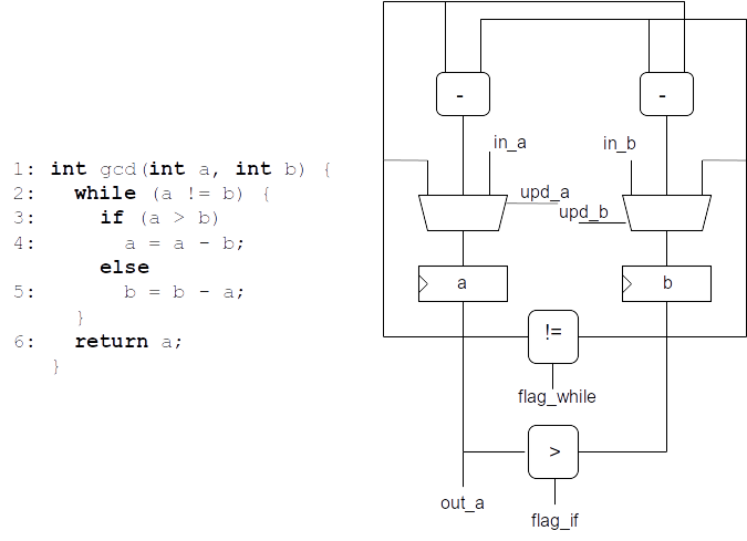 †Shaumont
19. Designing the Controller
- The controller unit is responsible for operating the data path elements
- The CFG directly translates to a finite-state machine (FSM)
- The controller together with the datapath then represent a Finite-State Machine with Datapath FSMD
- FSMD may be used to represent any algorithm intended for single clock domain hardware. FSMD will be discussed more later.
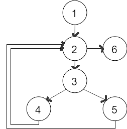
Example: GCD
CFG:
- next state logic directly from CFG with conditions
- control outputs are added to each state to complete the FSM
- a decoder implemented as a lookup table can help
 †Shaumont
Controller State machine and Datapath:
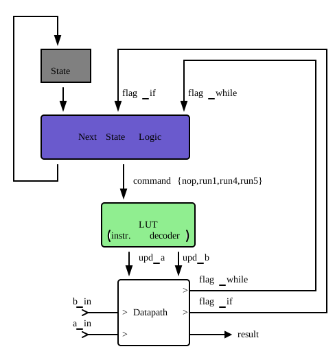
LUT as instruction decoder: The state machine could be design to directly output control signals, but control design can be abstracted from commands using a translation block called a decoder
design abstraction: updates to datapath control encoding can be handle by changes to decoder rather than controller
- especially useful when the controls are more numerous than the number of commands
instruction upd_amux controlupd_bmux controlnop (a) use previous (b) use previous run1 ( a_in) use input( b_in) use inputrun4 ( a-b) use sub(b) use previous run5 (a) use previous ( b-a) use sub
20. Single Assignment Code: Blocks of Code Per Clock Cycle
- Previous implementation assumed only at least one line of code per clock cycle
- Need method to identify multiple lines of code to be executed in a clock cycle
- The primary approach is using blocks of code representing Signal Assignment Code where each variable is assigned once. We need to examine the question, “When can multiple lines of code be executed in a clock cycle?”
- This is related to writing a proper block of Verilog code that represents combinatorial logic terminated by one set of register updates in a cycle
Basic Single Assignment Code
Simple Arithmetic Example:
Code
a=b+1;
a=a*3;
This is the same as
a = (b+1)*3;
- This only assigns
a, and there is a single assignment to it. - It can be implemented in hardware in a single cycle with \[\rm \text register\,b \rightarrow (+1 ) \rightarrow ( x3 ) \rightarrow register\,a\]
Using MERGE to construct Single Assignment Code
Original Code
int gcd(int a , int b) {
  while (a!= b) {
    if (a> b)
      a = a-b;
    else
      b=b-a;
    }
    return a;
}
int gcd(int a1 , int b1) {
 while (MERGE(__?a1:a2)!=MERGE(__?b1:b2){
    a3 = MERGE(__?a1:a2);
    b3 = MERGE(__?b1:b2);
    if (a3> b3)
      a2 = a3-b3;
    else
      b2 = b3-a3;
    }
    return a2;
}
†Shaumont
- Fill in conditions to complete the code
- For this iterative algorithm, the single-assignment code helps reveal
that one full iteration of the algorithm can be completed without any
intermediate registers
- implies that one full iteration might be computed in combinational
logic if timing allows
- i.e. implies that one full iteration might be computed per clock cycle if timing allows
- implies that one full iteration might be computed in combinational
logic if timing allows
21. Single-Assignment Code Hardware Implementation
- Single Assignment Code allows examination of data dependencies and hardware resources such as what can be done in a single clock cycle (combinatorial) and where a register is required.
- These concepts are also important when writing behavioral HDL code in Verilog or VHDL.
- In the previous code, multiple lines may be computed in one cycle
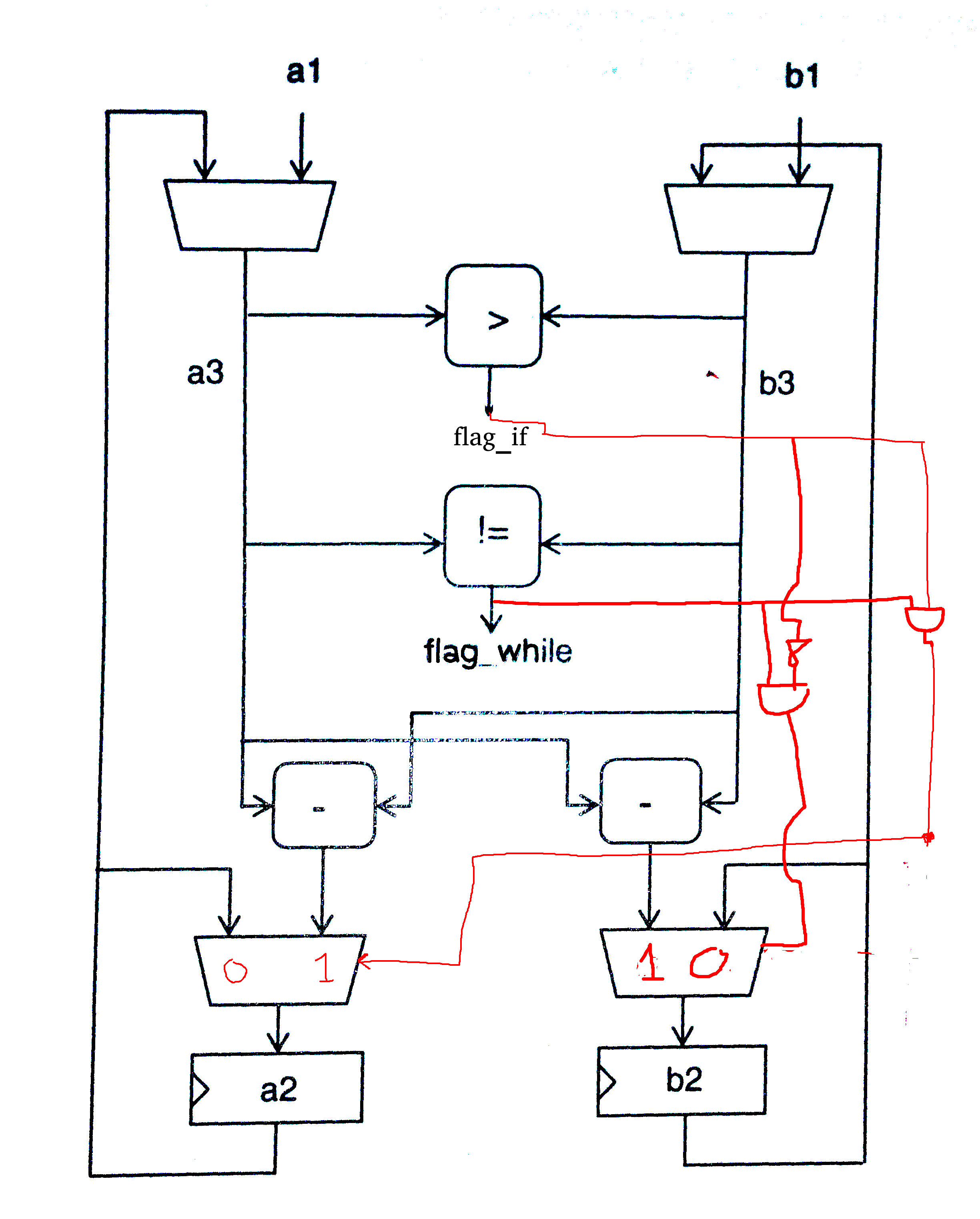
- modifying the datapath or providing forwarding of the the flags allows for combining the comparison, subtraction, and update
- The logic in red could be implemented in either the controller or
the datapath
- Later we'll see that implementing the logic in a REPROGRAMMABLE controller allows for datapath reuse,
- whereas implementation in the datapath could be more optimal but tailors the datapath rigidly for the application, making the datapath less flexible
22. Forward Discussion: Synthesis of Multicycle Operations
- It is typical to employ multi-cycle operations to reduce hardware through resource sharing (reuse of hardware in difference clock cycles) and reduce the critical path lengths.
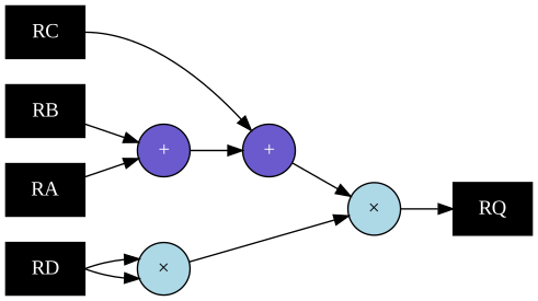
- Consider different implementations of \(Q=(A+B+C) \times D^2\)
- A goal of this course is to know how to implement any of these following approaches with a state machine descriptions, modifiying path contraints in contraints specification files as needed
- Single Cycle, Two Multipliers:
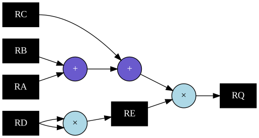
- Two Cycle, Two Multipliers, Reduced Critical Path:
- Three Cycle, Two Multipliers, Reduced Critical Path, Fully Pipelined
- Note need for register RF:

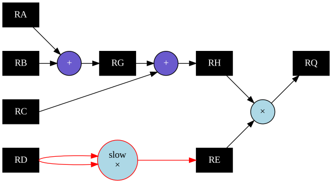
- Three Cycle, One Fast Multiplier, One Slow Multipler, Reduced Critical Path, Partial Pipelined
- The red path can run slower, a timing constraint will be discussed later in the course that allows the path to settle in two clock cycles
- Three Cycle, One Fast Multiplier:
- Resource Sharing
