L02 – Verilog Events, Timing, and Testbenches
Ryan Robucci1. References
- (Cummings 2000) Some examples are borrowed: Cummings, Clifford E.
"Nonblocking assignments in verilog synthesis, coding styles that
kill!." SNUG (Synopsys Users Group) 2000 User Papers (2000).
http://www.sunburst-design.com/papers/CummingsSNUG2000SJ_NBA.pdf
- (IEEE Std 1364-2005) IEEE Standard for Verilog Hardware Description Language,” in IEEE Std 1364-2005 (Revision of IEEE Std 1364-2001) , vol., no., pp.1-590, 7 April 2006 doi: 10.1109/IEEESTD.2006.99495 Abstract: The Verilog hardware description language (HDL) is defined in this standard. Verilog HDL is a formal notation intended for use in all phases of the creation of electronic systems. Because it is both machine-readable and human-readable, it supports the development, verification, synthesis, and testing of hardware designs; the communication of hardware design data; and the maintenance, modification, and procurement of hardware. The primary audiences for this standard are the implementers of tools supporting the language and advanced users of the language. URL: http://ieeexplore.ieee.org/stamp/stamp.jsp?tp=&arnumber=1620780&isnumber=33945
- Reference material for timing examples: (Cummings 1999) Cummings, Clifford E. "Correct Methods for Adding Delays to Verilog Behavioral Models !." HDLCON 1999. http://www.sunburst-design.com/papers/CummingsHDLCON1999_BehavioralDelays_Rev1_1.pdf
2. An Event-Driven Modeling and Simulation Language also used for Synthesis
- We emphasize use of Verilog as a hardware description language for synthesis, but it is a general event-driven simulation modeling language
- Verilog is event driven, events are triggered to cause evaluation events to be queued which cause updates to be queued which may in turn serve as triggers for other events to be queued.
- Events are entered into a priority queue for processing. Event
elements in the priority queue are removed and processed according to
two rules
- earliest time first
- then first come first serve stack behavior
- Nondeterminism of concurrent statements: By default, individual assignment statements and blocks in a module are considered to be concurrent. This means that there evaluation may be queued in any order if triggered.
- Certain coding guidelines constrain the use of the language to ensure
deterministic behavior in simulation and are known to map to hardware
with the same behavior
- Most of these issues relate to concurrency
3. Verilog Language
Being a hardware description and modeling language, Verilog supports modeling of concurrency as well as time.
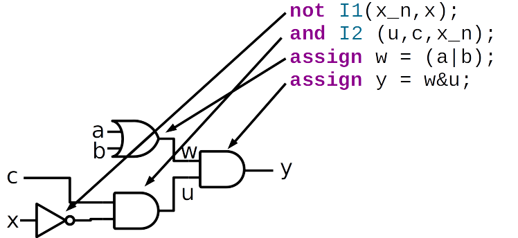
- Inclass: example flow of value propagation and events \({a,b,c,x}={1,1,1,1} \rightarrow {a,b,c,x}={1,1,1,0}\)
4. Timing
- Timing and delay are intrinsic aspects of physical circuits and are important concepts for hardware modeling
- Delay in a logic path might be a parasitic effect, and must be analyzed to ensure the circuit can operate fast enough.
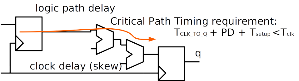
- Delay in the logic path also helps prevent race conditions if the clk arival at the downpath register is slightly delayed
5. Timing (Ex. Pulse Circuit)
Other times, delay is fundamental to how a circuit works.
- In the circuit below delay is necessary for the circuit to generate a pulse.
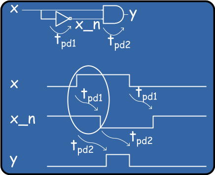
Structural Example with delays indicated with #:
module  pulser(y, x);
  input   x;
  output  y;
  wire    x_n;

  and     #50 (y, x, x_n)
  not     #3 (x_n, x);
endmodule
6. Concurrent Operation
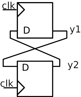
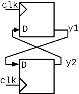
Describing Concurrency is another feature of an HDL The following code
attempts to model a swap of y1 and y2, as in
y1 = old y2 concurrently with y2 = old y1
Concurrent Assignment (Cummings 2000):
module fbosc2 (y1, y2, clk, rst);
  output y1, y2;
  input clk, rst;
  reg y1, y2;

  always @(posedge clk or posedge rst)
    if (rst) y1 <= 0; // reset
    else y1 <= y2;

  always @(posedge clk or posedge rst)
    if (rst) y2 <= 1; // preset
    else y2 <= y1;
endmodule

This is a case where handing of concurrency, is critical as two interdependent updates are at once
7. Verilog Execution Model
- A Verilog Simulation involves processing events from different queues that have different priorities
- Most events in the queues can be describe as evaluation or update
events
- Evaluation events involve processing or execution. These events can enable other events to enter the active queue, often it enters value assignment events into the queue.
- Update events involve making a value assignment to a variable. These in turn may implicitly enable evaluation events that are sensitive to the changed variable
8. The stratified event queue
The IEEE standard identifies 5 regions for events to live:
- Active events: in queue ready for execution in current simulation time. The Nondeterminism property states that the order that they are removed is not specified. One effect is that concurrent statements and blocks are not guaranteed execution in any order. Furthermore, blocks of behavioral statements may be returned to the active queue at any point even if only partially completed. This allows interleaving of process execution but also unpredictable behavior for concurrent processes with ill-coded communication paths between them.
- Inactive events: to be processed at the end of the current simulation time after any active events in the queue. An explicit zero delay (#0) is a way to force an event to be transferred to the inactive event queue.
- Nonblocking assign update events: to be processed at the end of the current simulation time after active and inactive events in the queue. They are processed in the order they are added to the queue.
- Monitor events: to be processed if no active, inactive, or nonblocking assign update events are in the queue. These events do no create any other events.
$monitorand$strobesystem tasks generate monitor events. - Future events: active, inactive and nonblocking assign update events scheduled with a future time
9. IEEE Specification of Event Handling
(Quoted from IEEE Std 1364-2005 with colors added)
while (there are events){
  if (no  active events){
    if      (there are  inactive events){
           activate all inactive events;
    } else if(there are  nonblocking assign update events){
           activate all nonblocking assign update events;
    } else if(there are   monitor events){
           activate all monitor events;
    } else{
          advance T to the next event time;
          activate all inactive events for time T;
    }
  }

  E = any active event;
  if (E is an update event){
    update the modified object;
    add evaluation events for sensitive processes  to event queue;
  }else { /* shall be an evaluation event */
     evaluate the process;
     add update events  to the event queue;
  }
}
10. Bad Parallel Blocks
Bad Concurrent Assignment (Cummings 2000):
module fbosc1 (y1, y2, clk, rst);
  output y1, y2;
  input clk, rst;
  reg y1, y2;

  always @(posedge clk or posedge rst)
    if (rst) y1 = 0; // reset
    else y1 = y2;

  always @(posedge clk or posedge rst)
    if (rst) y2 = 1; // preset
    else y2 = y1;
endmodule
- This code attempts to model a swap of y1 and y2
- Timing of execution of parallel always blocks is not guaranteed in simulation – though synthesis will probably work since synthesis approaches each always blocks somewhat independently at first
11. Simulation of parallel blocks

12. Good Parallel Blocks
Will not only synthesize correctly, but also simulate correctly:
Good Concurrent Assignment (Cummings 2000):
module fbosc2 (y1, y2, clk, rst);
  output y1, y2;
  input clk, rst;
  reg y1, y2;

  always @(posedge clk or posedge rst)
    if (rst) y1 <= 0; // reset
    else y1 <= y2;

  always @(posedge clk or posedge rst)
    if (rst) y2 <= 1; // preset
    else y2 <= y1;
endmodule
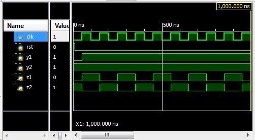
13. Sim Example
module amb_parallel_swap();

  reg clk, rst;
  reg y1, y2;
  reg z1, z2;

 initial clk = 0;
 always #50 clk = ~clk;

 initial begin
  rst = 1;
  #10;
  rst = 0;
 end


  initial begin
   #1000 $finish;
  end
 always @(posedge clk , posedge rst)
  if (rst) y1 = 0; // reset
  else y1 = y2;

always @(posedge clk , posedge rst)
  if (rst) y2 = 1; // preset
  else y2 = y1;
always @(posedge clk , posedge rst)
  if (rst) z1 <= 0; // reset
  else z1 <= z2;

always @(posedge clk , posedge rst)
  if (rst) z2 <= 1; // preset
  else z2 <= z1;
endmodule
14. Continuous Assignment
Continuous assignment statements enable (a.k.a. schedule or trigger) an evaluation event when any source element of the RHS expression changes. Upon any expression's resulting value change, an update event for the LHS is added to the active queue.
assign {cout,b} = d+a;
Left-hand-side (LHS) expression: {cout,b} Right-hand-side (RHS) expression: d+a;
An initial evaluation always occurs at time zero to propagate constant values. The various cascades of dependanceis cause other expresssions and procedural code in the HDL models to be evaluated at time zero as a result. In the the following, an initial evaluation and assignment will occur, but no other update to a will happen in the simulation.
assign a=1;
15. Procedural continuous assignment
- Consider this topic not covered until future notice
- Involves keywords assign, force, deassign, release when specifically used inside procedural code
16. Switch (transistor-level) processing
- Not covered until future notice: switch modeling keywords such as tran, tranif0, tranif1,rtran, rtranif0, rtranif1
17. Blocking and Nonblocking Procedural Assignment with Delays
Blocking assignments cause an immediate evaluation of the right hand side. If delay is provide, then the assignment to the left-hand-expression is scheduled for a future time unless the delay is 0 and in which case the assignment event is entered into the inactive queue. If no delay is specified the statement performs the assignment and returns immediately. Once the assignment is performed, any change will enable any events dependent on the value.
a = #D b+c;assignment delay D
Nonblocking assignments schedule an evaluation and assignment using the values of the inputs at the time of the scheduling. The event is placed in the nonblocking assignment update event queue for the current time or, if a delay is provided, a future time.
a <= #D b + c;assignment delay D
- ⚠️ Warning Delays are for Simulation Only
- Delays are only used when modeling for simulation. They should not be used to describe characteristics to a hardware synthesis tool. Typically, all # delays are stripped from code before synthesis.
18. Procedural Blocking and Procedural Assignment Delay
In the delay-before-evaluation form (statement delay or evaluation delay), the delay essentially "sleeps" the process until another time before the following code is evaluated.
#D a = b + c;  //delay before evaluation
#D a <= b + c; //delay before evaluation
Code after these statements in a begin…end block will not execute until after the delay, nor will the block pass control
Assignment delay schedules an assignment for a future time, though the RHS expression is evaluated using the values at the time of the scheduling.
a = #D b + c; delay before assignment, execution in begin..end block
does not progress until assignment event is handled, nor will the block
will pass control
a <= #D b + c; delay before assignment: RHS evaluation is followed by
scheduling a future nonblocking assignment event, execution within a
begin…end block progresses and control may be passed out of the block
Code example
initial #0 $display($time,"  a  b  y  z");

 initial begin
   $monitor($time,u8a,u8b,u8y,u8z);
   u8a=0; u8b=0;
   #5;
   #5 u8a = 1;
   #5 u8b = 1;
end

always@* begin
   $display($time,u8a,u8b,"       enter nonblocking");
   u8y <= #20 u8a+u8b;
   $display($time,u8a,u8b,"       leave nonblocking");
end

always@* begin
   $display($time,u8a,u8b,"       enter blocking");
   u8z = #20 u8a+u8b;
   $display($time,u8a,u8b,"       leave blocking");
end

initial #100 $finish;
Result
Simulator is doing circuit initialization process.
                 0  0  0       enter nonblocking
                 0  0  0       leave nonblocking
                 0  0  0       enter blocking           ***
 Finished circuit initialization process.
                 0  a  b  y  z
                 0  0  0  x  x
                10  1  0       enter nonblocking
                10  1  0       leave nonblocking
                10  1  0  x  x
                15  1  1       enter nonblocking
                15  1  1       leave nonblocking
                15  1  1  x  x
                20  1  1       leave blocking           ***
                20  1  1  0  0
                30  1  1  1  0
                35  1  1  2  0
Stopped at time : 100 ns : File "…/delay_tests.v" Line 56=
- * * * Delayed Blocking assignment prevented multiple calls.
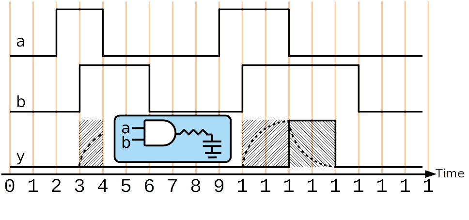
19. Inertial and Transport Delay
- Transport Delay maintains all transitions and delays them by a
specified amount. Models a delay like an ideal transmission line.
- Transport delay does not model pulse rejection described below.
- Inertial Delay also delays transitions, but it only maintains transitions to new states that are held for as long as the specified delay. Approximates models charging and pulse rejection.
Inertial Delay Pulse Rejection: pulses of a duration less than the specified inertial delay are rejected.

20. Inertial Delay Using Continuous Assignment (wire and SystemVerilog reg/logic)
The following are all examples of inertial delay on a wire.
delay with assign (continuous assignment)
Verilog/SystemVerilog
wire x_n;
assign #5 x_n = ~n;
SystemVerilog
logic x_n;
assign #5 x_n = ~n;
logic x_n;
assign #5 x_n = ~n;
delay in declaration (added to any assign delay)
wire #5 x;
assign x = ~x;
delay in the declaration of a wire with implicit continuous assignment
wire #5 x_n = ~n;
❌ syntax error: initialization syntax with logic/reg implies 1-time initial assignment and is not compatible with delay:
logic #5 x_n = ~n;
...
  module tb;
     logic a = 1;
     logic b = 1;
     //logic #1 a_n = ~a;          //syntax error no delay on logic/reg declaration
     logic  b_n = ~b;
     logic a_n ;
     assign #1 a_n = ~a;

     initial begin
        $monitor("%04t",$time, "  a=",a,"  a_n=",a_n, "  b=",b,"  b_n=",b_n);
        #0;
        a=0;b=0;
        #10;
        a=1;b=0;
        #100;
        $finish;
     end

  endmodule // tb
 0  a=0  a_n=x  b=0  b_n=0
 1  a=0  a_n=1  b=0  b_n=0
10  a=1  a_n=1  b=0  b_n=0
11  a=1  a_n=0  b=0  b_n=0
Declaration delay augmented by assignment delay
In this example, the inertial delay to
ais fromxis 3wire #2 a; assign #1 a = x;
In this example, the inertial delay to
ais4and forbis3:wire #3 a; wire #2 b; assign #1 {a,b} = {x,x};
21. Inertial Delay using Primitives
Inertial delay may be provide to primitives using the simplist form of the delay operator.
wire y;
and #3 I1(y,a,b);
In this next example, the inertial delay to y is 4 since delay provide in the declaration is added.
wire #1 y;
and #3 I1(y,a,b);
22. Pulse Rejection is Based on the Result/Output (not input pulse-width)
The pulse rejection behavior is based on the result, not the inputs. The result of an expression to be assigned must maintain a new value for the specified time.
wire y;
assign #2 y = a&b;
wire y;
and #2 I1(y,a,b);
wire y;
assign #3 y = |{a,b,c};
wire y;
or #3 I1(y,a,b,c);

23. Rising and Falling Delay Can Be Different
Separate delays can be provided for rising and falling output edges
wire y;
and #(3,2) I1(y,a,b); //#(rising delay,falling delay)
| Transitions | Edge Type |
|---|---|
| 0 → 1, X→1 Z→1 | Rising Edge |
| 1 → 0, X→0, Z→0 | Falling Edge |
Other output edges (e.g. X→Z , 1→Z ) assume the minimum value between the of the rising and falling delays (2 in the example above)
Good Reference:http://verilog.renerta.com/source/vrg00011.htm
Min:Typical:MaxYou can also specify Min:Typ:Max delays which are selected by the simulator:
assign #(1:2:3) y = a & b;
assign #(2:3:4,1:2:3) y = a & b;
Good Reference: http://verilog.renerta.com/source/vrg00025.htm
24. Inertial Delay for reg
For a reg signal, to model inertial delay it is recommend to create a
delayed wire copy. Direct modeling of inertial delay is difficult
otherwise.
Augmenting reg with Inertial Delay:
wire c;
reg c_nodelay
assign #5 c = c_nodelay;
always @(b,d)
  c_nodelay = ~b|d;
end
25. Modeling of Delay for Sequential Logic
- Study these examples one-by-one as practice to understand Verilog; and reference when trying to model delay (no need to memorize)
- Note that I am not using alwaysff or alwayscomb since this a modeling exercise and not for synthesis
✔️ Good
parameter TC2Q;
reg q;
always @(posedge clk)
  q <= #TC2Q ~b;
- Evaluate now, assign later Models Clk-to-Q delay
❌ Bad
❌
parameter TC2Q; reg q; always @(posedge clk) q = #TC2Q ~b;=
- Evaluate now, assign later Bad: Nondeterminism of assignment at later time
❌ (delay the clock)
parameter TC2Q;
reg q;
always @(posedge clk)
  #TC2Q q <= ~b;
- Evaluate after delay then assign
- Models a delay in the clock signal. Not recommended, better to create and use a delayed clock using other delay methods
❌
parameter TC2Q;
reg q;
always @(posedge clk)
  #TC2Q q = ~b;
- Evaluate after delay then assign
- Bad: Nondeterminism of assignment at later time
26. Modeling of Transport Delay, sometimes for Combinational Logic
| inertial delay | transport delay | |
|---|---|---|
| modeling a gate driving a capacitor load at the output of a circuit | modeling delays through several combinational logic gates, e.g. combinatorial path delay |

✔️ Good for Simulation Model
✔️ Trasport Delay for combinational logic
parameter D;
reg y;
always @(a,b)
  y <= #D a&b;
```verilog
always @(y)
  y_delayed <= #D y;
- Evaluate now, assign later
- Can be use to model transport delay for combinatorial logic or a delayed signal such a from a transmission line
- Note that non-blocking assignment is required to to prevent blocking of re-evaluation
Delay-Free and Delayed Signals for Simulation and Synthesis
- My preference for casual simulation modeling is to model the transport delay separately
- Code is still compatible with synthesis
...
   parameter D;

   logic y;         //wire or SystemVerilog reg
   logic y_nodelay; //reg


   assign #D y = y_nodelay;
  always @(a,b)
     y_nodelay = a&b;
   ...
   ...
or
logic y_delayed; //wire or SystemVerilog reg
assign #D y_delayed = y;
❌ Bad
❌
parameter D;
reg y;
always @(a,b)
  y = #D a&b;
- Evaluate now, assign later
- Bad: Blocks reevaluation (ignores input update events)
❌
parameter D;
reg y;
always @(a,b)
  #D y <= a&b;
- Evaluate later and assign
- Bad: Blocks reevaluation
❌
parameter D;
reg y;
always @(a,b)
  #D y = a&b;
- Evaluate later and assign
- Bad: Blocks reevaluation
27. Simulation Use of RHS non-blocking assignment delay
- RHS non-blocking delays may be conveniently used in testbenches to schedule several delayed assignments (not something I use)
Example 1:
initial begin
  a <= 0;
  a <= #10 255;
  a <= #20 22;
  a <= #30 10;
  b <= 'bx;
  b <= #1 1193;
  b <= #10 122;
  c <= #10 92;
  c <= #15 93;
end
Example 2: delays relative to rst signal change
initial begin
  a = 0;
  b = 0;
  c = 0;
  wait (rst==0);
  a <= #10 255;
  a <= #20 22;
  a <= #30 10;
  b <= #1 1193;
  b <= #10 122;
  c <= #10 92;
  c <= #15 93;
end
28. Procedural Timing Controls
- Delay control: delay between encountering the expression and when it
executes.
- Introduced by simple
#
- Introduced by simple
- Event control: delay until event
- Explicit Events are named events that allow triggering from other
procedures
- A named event may be declared using the keyword
event - The event control operator @ can be used to hold procedural code execution operator -> triggers the event
- A named event may be declared using the keyword
- Implicit events are responses to changes in variables
- The event control operator @ can be provided a sensitivity list
with variables and on optional event selectivity using keywords
posedgeandnegedge
- The event control operator @ can be provided a sensitivity list
with variables and on optional event selectivity using keywords
- Explicit Events are named events that allow triggering from other
procedures
event triggerName;
@(triggerName);
-> triggerName;
29. Event Control Operator
The event control operator may be provided with variable multiple variables using comma separation. (older syntax is to us or)
@(a,b,c)
💀 Old Syntax
@(a or b or c)
Negedge and posedge restrict sensitivity to the following transitions
@(posedge clk or negedge en)
- Negedge Bit Transitions:
- 1→ 0
- 1→ x or z
- x or z → 0
- Posedge Bit Transitions:
- 0 → 1
- x or z →1
- 0 → x or z
- Multibit: When posedge and negedge modify a multi-bit operand , only the lsb is used to detect the edge.
1010 -> 0001    posedge


1011 -> 1110    negedge
30. Level-sensitive event control using wait
- The wait statement suspends execution until a condition is true.
- It can be considered as a level-sensitive control since it doesn't wait for a transition edge.
Comparison of wait to posedge:
verilog @(posedge clk)even if clk is already true, wait for next rising edgewait (clk);
if clk is already true, produce without delay
Example to change data on the falling clock edge following the event in which a variable exceeds the value 10:
wait(a>10);
@ (negedge clk);
data<=data+1;
31. Repeat Construct
Repeat keyword can be used to create repetition of statements or delay operations
Repeat "Loop"
repeat (3) begin
   count = count +1;
   $display ("Count" : count);
end
Repeat timing control
Any timing control may be modified so as to be repeated/multiplied, by using the keyword repeat
Dynamic Repeat (simulation run-time variable)
repeat (count) @ (event expression)
If count is positive, repeat the timing control that number of time. If count is equal or less than 0, skip
Cycle Delay
Wait fot 10 clk rising edges before proceeding execution:
repeat (10) @ (posedge clk);
do_stuff
Delay an assignment by 5 clk edges
a <= repeat(5) @(posedge clk) data;
Delay Multiplicity
Delay an assignment by 5 inverter delays:
parameter INV_DELAY = 4.5;
a <= repeat(5) #INV_DELAY data;
32. initial and always
The initial construct is used to denote code to be executed once at the beginning of the simulation.
The always construct causes code to run repeatedly in an infinite loop. It is only useful with a delay or control construct, otherwise will create a zero delay infinite loop that can block time progression in simulation
This would run infinitely and stall the simulation time:
always x=a&b;
This prints endlessly in the beginning of the simulation:
always begin
  $display(“hello %0t”);
end
0 : hello
0 : hello
0 : hello
0 : hello
0 : hello ...
33. Sequential and Parallel Blocks
- Sequential procedural blocks are wrapped with
begin...end - Parallel procedural blocks are wrapped with
fork...join- Statement Delay control is relative to entering the block
- Control passes out of the block when the last statement, which may be delayed in time, is completed
- Here is a mix, waiting for two three events before performing assignment
a=b:
begin
   x=y;
   fork
      @event ... ;
      @event ... ;
      @event ... ;
   join
   a = b;
end
- Don't confuse the term sequential code to mean coding a procedural block for sequential hardware
- sequential code refers to control flow of code which defines its functional interpretation, but it can describe the functionality of combinatorial hardware and/or sequential hardware
- sequential hardware would refers to inferred hardware
34. Sim Using Test Bench
DUT:
module Nand_Latch_1 (q,qbar,preset,clear);
  output q, qbar;
  input preset,clear;
  Nand1 #1 G1 (q,preset,bar);
  G2 (qbar,clear,q)
endmodule
Testbench:
module test_Nand_Latch_1; // Design Unit Testbench
  reg       preset, clear;
  wire       q, qbar;
  Nand_Latch_1 M1 (q, qbar, preset, clear);// Instantiate DUT
  initial // Create DUTB response monitor
   begin
    $monitor ($time,
              "preset = %b clear = %b q = %b 1 qbar = %b",
               preset, clear, q, qbar);
  end
  initial
  begin // Create DUTB stimulus generator
    #10    preset    =0;    clear =1;
    #10    preset    =1;   $stop;    // Enter, to proceed
    #10    clear     =0;
    #10    clear     =1;
    #10    preset    =0;
  end
  initial
    #60    $finish ; // Stop watch
  end
endmodule
Results:
 0 preset = x clear = x q = x qbar = x
10 preset = 0 clear = 1 q = x qbar = x
11 preset = 0 clear = 1 q = 1 qbar = x
12 preset = 0 clear = 1 q = 1 qbar = 0
20 preset = 1 clear = 1 q = 1 qbar = 0
30 preset = 1 clear = 0 q = 1 qbar = 0
31 preset = 1 clear = 0 q = 1 qbar = 1
32 preset = 1 clear = 0 q = 0 qbar = 1
40 preset = 1 clear = 1 q = 0 qbar = 1
35. Time Unit and Resolution Directive
clocks can be set to realistic frequencies for timing simulation
parameter PERIOD=4;

initial clock = 1’b0;
always #(PERIOD/2) clock = ~clock;
unit and precision for the time quantity is defined by a derective at the top of a file
`timescale unit/resolutiontime unit: what unit the delays should be interpreted asprecision: what the precision is used use for each timing event
Examples:
example :
`timescale 1ns/1ps
Then
#17.0402represents 17.040 nsexample
‘timescale 1.0ns/100ps
...
 #(10/3.0) clock = 1'b1
10/3.0 = 3.33…ns = 3333.3333….ps, but delay in simulation is rounded to 3300 ps because resolution is 100ps
36. Generating a clock in a testbench
50% duty cycle:

initial begin
  clk = 0;
end
always begin
  #5 clk = 0;
  #5 clk = 1;
end
initial begin
 clk = 0;
end

always begin
  #5 clk = ~clk;
end
The procedural construct forever can be used the create an infinite loop:
initial begin
  clk = 0;
  forever begin
    #5 clk = ~clk;
  end
end
37. Generating an irregular clock in a testbench

initial begin
  clk = 0;
  forever begin
    repeat (16) begin
      #5 clk = ~clk;
    end
    #20;
  end
end
The procedural construct repeat can be used to create a limited loop
38. Testing all combinatorial inputs using a counter
- Here, the first input ,
a, is changed every5time units, cycling every10time units - Each subsequent input at half the rate of the previous
reg a,b,c,d;
initial begin
 a <= 0; b <= 0;
 c <= 0; d <= 0;
end

always begin
  #5 a <= ~a;
end
always begin
  #10 b <= ~b;
end
always begin
  #20 c <= ~c;
end
always begin
  #40 d <= ~d;
end
The same effect can be achieved using a counter:
wire a,b,c,d;
reg [3:0] count;
initial begin
  count = 0;
end

assign {a,b,c,d}=count;
always begin
  #5 count = count+1;
end
39. Testing memory
wire data_out;
reg write;
reg [3:0] addr;
reg [7:0] memory_buffer [0:15]; // 16 entries 8 bit #'s
reg [7:0] data_in;
integer i; integer file;
my_mem DUT (data_out,data_int,addr,write);
initial begin
    $readmemh("memory_hex_in.txt", memory_buff); //init memory_buff from file
    file = $fopen(“memory_hex_out.txt”);  //open a file for writing results
    #5 write <= 0; addr <= 0;
    for (i=0; i<16; i++) begin //write to mem
        #5 write <= 0; data_in <= memory_buff[i]; addr <= i;
        #5 write <= 1;
    end
    #10 write <= 0;

    //reading and writing to file
    for (i=0; i<16; i++) begin
        #5 addr <=i;
        $fstrobe(file,“%2H”,data_out);
    end
    $fclose(file);
end
The procedural construct for can be used to create simulation loops.
40. Stimulus Generation
- it is recommended to use non-blocking for primary inputs update by clk
this models registers driving the system
- emulates FFs driving inputs, provide deterministic simulation
design under verification, a D-flip-flop
always @(posedge clk)
   driverA <= a;
- emulates FFs driving inputs, provide deterministic simulation
- test bench that applies stimuli to design's primary inputs
❌
always @(posedge clk) begin
 D = memory_buff[i]; // non-determinism
 i=i+1;
end
✔️
always @(posedge clk) begin
 D <= memory_buff[i]; // good
 i=i+1;
end
best to control timing of inputs from a base clock rather than maintain delays
wait(ready==1'b1);
@ (posedge clk);
data<=data+1;
repeat (10) @ (posedge clk);
done<=1'b1;
Input Driver Stage Modeling in Testbench using non-blocking assignments to primary inputs :
\(\rightarrow\) drives
DUT with primary inputs a,b,c:
...
  module tb;
       ...
       logic a,b,c,clk,u,v,V;
       or_or_q dut(.*);
       ...
       always @ (posdge clk) begin

          a<=generated_a;
          b<=generated_b;
          c<=generated_c;
       end
       ...
       ...
Timing Simulation
                        |cycle 1  | cycle 2 | cycle 3 |
clk            ────┐    ┌────┐    ┌────┐    ┌────┐    ┌───
                   └────┘    └────┘    └────┘    └────┘
                        ▲         ▲         ▲        ▲
driverA        ─────────┐(0)      ┌───────────────────┐
                        └─────────┘                   └───
DUT.a (comb)   ───────────┐(0)      ┌───────────────────┐
                          └─────────┘                   └─
DUT.u (comb)   ──────────────┐(0)      ┌──────────────────
                             └─────────┘
DUT.v (comb)   ────────────────┐(0)      ┌────────────────
                               └─────────┘
DUT out reg. V ────────────────────┐(0)      ┌─────────────
                                   └─────────┘
                        ▲         ▲         ▲        ▲
Zero-Delay Simulation (a.k.a. functional/behavioral)
Sometimes called a behavioral / functional simulation since it is checking the digital functionality on a cycle-accurate basis. Without timing the picture can be confusing:
                        |cycle 1  | cycle 2 | cycle 3 |
clk            ────┐    ┌────┐    ┌────┐    ┌────┐    ┌───
                   └────┘    └────┘    └────┘    └────┘
                        ▲         ▲         ▲        ▲
driverA        ─────────┐(0)      ┌───────────────────┐
                        └─────────┘                   └───
DUT.a (comb)   ─────────┐(0)      ┌───────────────────┐
                        └─────────┘                   └───
DUT.u (comb)   ─────────┐(0)      ┌───────────────────┐
                        └─────────┘                   └───
DUT.v (comb)   ─────────┐(0)      ┌───────────────────┐
                        └─────────┘                   └───
DUT out reg. V ───────────────────┐(0)      ┌─────────────
                                  └─────────┘
                        ▲         ▲         ▲        ▲
Zero-Delay Simulation with input transitions on negative clock edge
for functional simulation (no timing) may use negative edge to enhance readability, but don't forget to revert before sub-cycle timing is modeled, otherwise the intervals of positive clock phase are misused
wait(ready==1'b1);
@ (negedge clk);
data<=data+1;
repeat (10) @ (negedge clk);
done<=1'b1;
For behavioral simulation without timing, might use negedge clk negedge for input changes: All input changes aligned with negedge clock and the associated processing is in the same cycle at the negdge with new updates computed and prepared to be loaded into registers at the end of the cyle and used in the following
...
  module tb;
       ...
       logic a,b,c,clk,u,v,V;
       or_or_q dut(.*);
       ...
       always @ (posdge clk) begin
         automatic logic generated_a,generated_b,generated_c;
         .../*generate inputs*/....

         @(negedge clk);

         a<=generated_a;
         b<=generated_b;
         c<=generated_c;
       end
       ...
       ...
       ...
                        |cycle 1  | cycle 2 | cycle 3 |
clk            ────┐    ┌────┐    ┌────┐    ┌────┐    ┌───
                   └────┘    └────┘    └────┘    └────┘
                        ▲         ▲         ▲        ▲
                   ▼         ▼          ▼         ▼
data in  x     ──────────────┐(0)      ┌──────────────────
                             └─────────┘
DUT.a (comb)   ──────────────┐(0)      ┌──────────────────
                             └─────────┘
DUT.u (comb)   ──────────────┐(0)      ┌──────────────────
                             └─────────┘
DUT.v (comb)   ──────────────┐(0)      ┌──────────────────
                             └─────────┘
DUT out reg. V ───────────────────┐(0)      ┌─────────────
                                  └─────────┘
                        ▲         ▲         ▲        ▲
                   ▼         ▼          ▼         ▼
                             ^
                             a strobe here will capture all recomputed
                             combinatorial signals and prepared results based on system state and inputs
                        ^         ^
                                  a strobe here will capture the new system state
                                  and combinatorial updates from new-state
In this type of simulation, use $monitor/ $strobe for debugging based on cycle states
- for output and other signals, either use
$monitor/$strobestatements timed with posedge of clk will display state values in registers and combinatorial signal updates from state changes$monitor/$strobestatements timed with negedge of clk will display new inputs, and combinatorial signal updates from input changes
41. Use $display for debugging procedural code
$display statements are best used for debugging sequential procedural that happens in one instant of time
always_comb  begin // (dep. on a,b,c)
   automatic logic [7:0] _u; //for RTL code use automatic for internal combinatorial variables
                             //  (akin to VHDL variable)
   $display("a(0)=",a);
   $display("b(0)=",b);
   _u = a * 2;           //u is twice a
   $display("u(0)=",u);
   _u = _u>b ? b:_u;       //u is limited/clipped to threshold b
   $display("u(1)=",_u);
   v = _u + c;           //v is min(a*2,b) + c
   $display("v(0)=",v);
end
42. final (System Verilog )
- complementary to
initial like initial procedures, but instead are called at the end of a simulation instead of at the begining keyword use:
final begin
   $display("Simulation Ended");
end
43. Use of Loops for Simulation Testbenches (behavioral-only) vs. Use of Loops for RTL Synthesis
- In the previous slides you were taught
for,foreverandrepeatin the context of simulation behavioral code for a testbench - going forward you are expected to know such use
- However you should NOT yet start using loops for synthesis.
- Rules for using loops in synthesis will be taught in a later lecture