Lecture 04
Verilog: Case-Statement Based State Machines
Ryan Robucci

• ESC/O-Key to see slide overview • ? to see help
 Printable Version
Finite State Machine (FSM)
- Characterized by
- A set of states
- A set of inputs and outputs
- A state transition function
- An output function

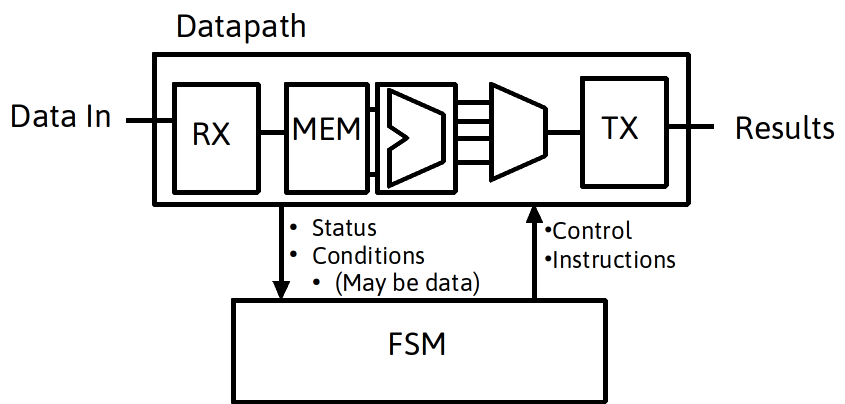
Finite State Machine with Datapath
- A very common framework being described and implemented is a Finite State Machine with a Datapath: a data path controlled by signals from a FSM
Books FSM Hardware Implementation
- suitable for implementation of algorithm with input and local variables stored in datapath register
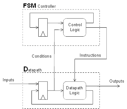
- Hardware Implementation:
- Current State held in a register
- Any additional status information held in status register
- Next-State and State Control Logic Determines next state and control signals based on registers
- Datapath implements operations on data under control of sate control logic
Software and Hardware
- If available customizable hardware is fast, and control logic is difficult to describe, a good mix can be software for control and hardware for calculations. We will see later approaches that use a general purpose processor for control.

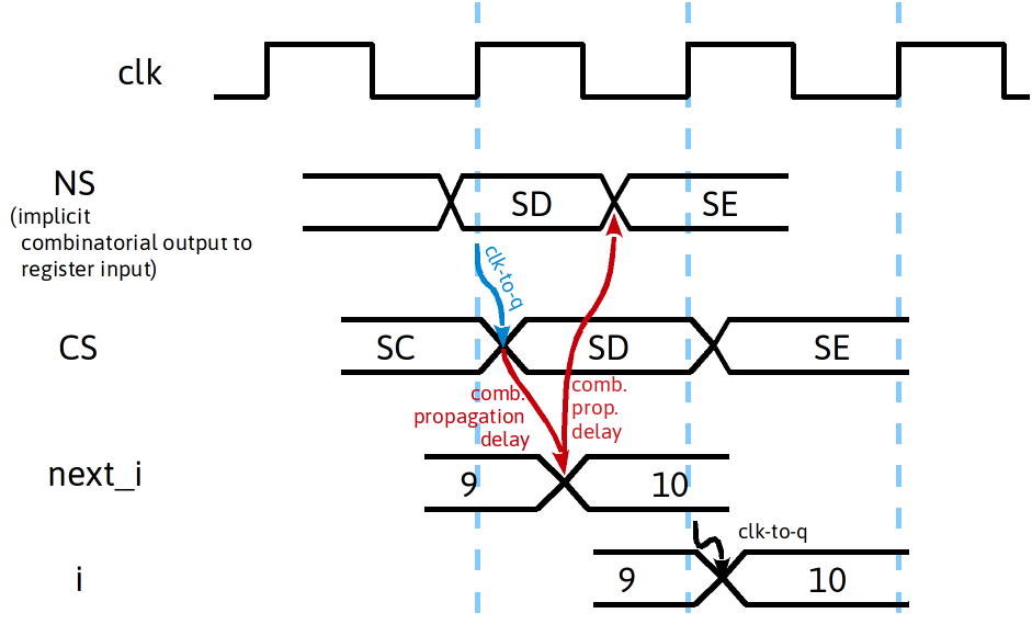
Temporal Processes of statemachine
ꭝ
- Just after clock edge, state variables are updated. For controller this means that a state-transition is complete and state registers holds the new current state. For the data path, this means that the register variables are updated as a result of assigning (algebraic, boolean, logical, etc...) expressions to them.
- Controller FSM Combines the control state and the data-path state to evaluate the new next state for the, at the same time it will also select what instructions should be executed by the datapath
- The datapath FSM will evaluate the next-state for the state variables in the datapath, using the updated datapath state as well as the instructions received from the control FSM
- Just before the next clock edge, both the control FSM and the datapath FSM have evaluated and prepared the next-state value for the control state as well as the datapath state
Algorithmic Statemachines
- However, encoding datapath operations WITHIN in the statemachine description with the controller instead of coding them in a separate block is sometimes better.
- It is common to see "algorithmic" statemachines described with control and computation embedded in the same procedural block. These are modules which perform complex computations over multiple cycles and require internal registers/memory.
- We’ll first focus on control state machines first, with an emphasis on timing and external status and control signals then discuss computational statemachines
Data-Flow Graph
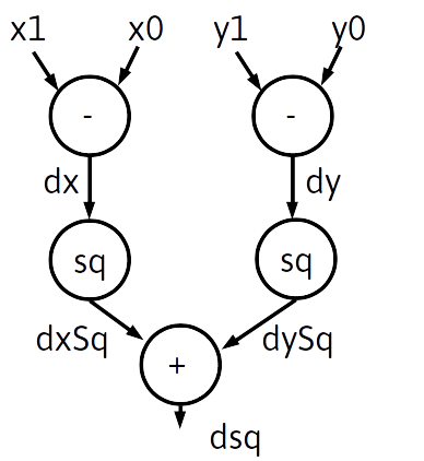
- Data-Flow Graphs represents dependencies among operations in the process of an arithmetic algorithm (more compact than a full state diagram).
- A algorithmic state machine performs one or more operations in a state (i.e. clock cycle) while satisfying the required order dependencies from the graph
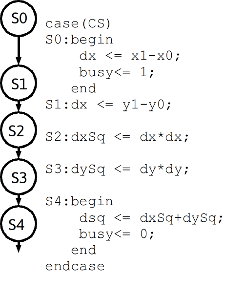
- Ex: Draw the Datapath and Identify Status and Control as well as Pre-Register data names
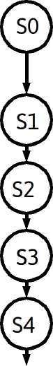
case(CS)
S0:begin
    dx <= x1-x0;
    busy<= 1;
   end
S1:dx <= y1-y0;
S2:dxSq <= dx*dx;
S3:dySq <= dy*dy;
S4:begin
    dsq <= dxSq+dySq;
    busy<= 0;
   end
endcase
note the explicit state register and the additional extended state registers
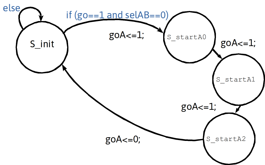
Unconditional Delay Using Extra States
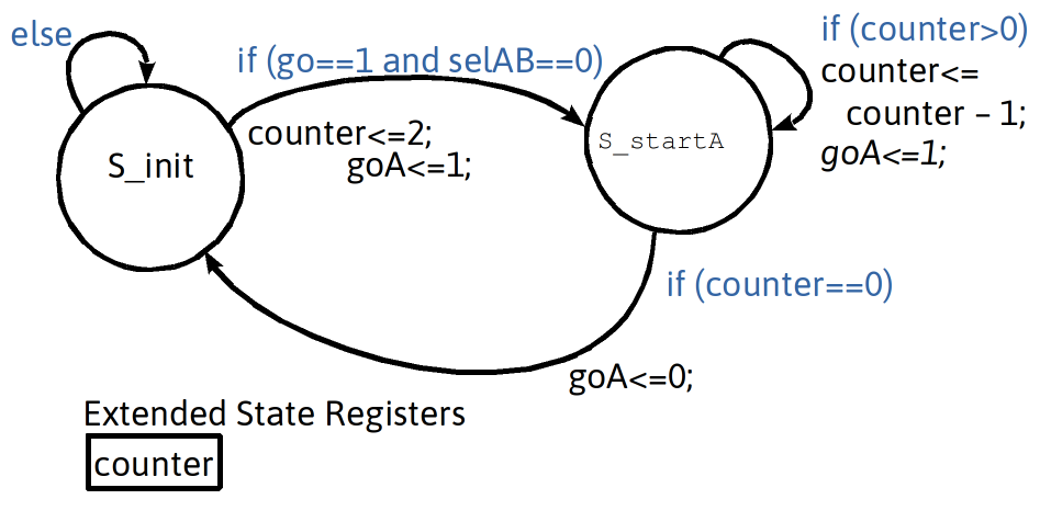
Unconditional Delay Using Extended State Register Variable : Counter
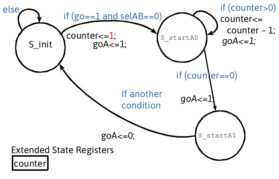
Minimal Pause: Delay + Conditional Exit Using An Extra State (unconditional delay +conditional exit)
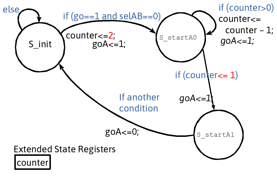
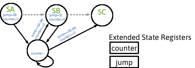
Minimum Wait: Delay + Conditional Exit Using Extended State Register Variable Counter
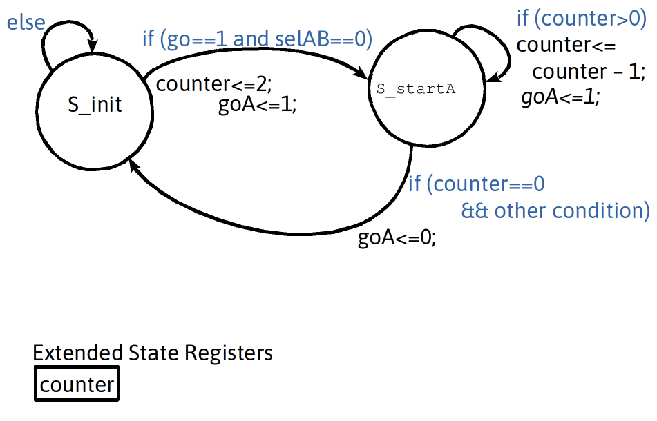
Programmable Wait State
- Explicit Top-Level States vs Programmable State
- Explicit
- Programmable
- Explicit
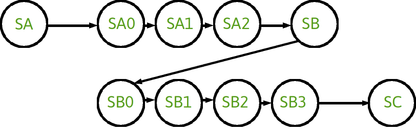
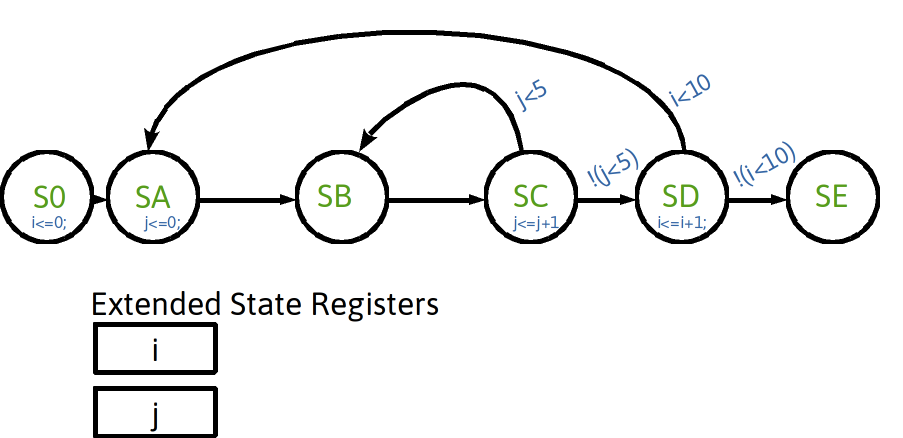
“For Loop” State Machine
- Extended-state registers can help implement loop behaviors
- Example: create outer loop with 10 iterations and inner loop with 5 iterations
Drawing Possible Hardware
Realizations of i,j registers and support hardware
- After examination of the state diagram, three required behaviors are desired: , ,
- A primary FSM will generate the control signals
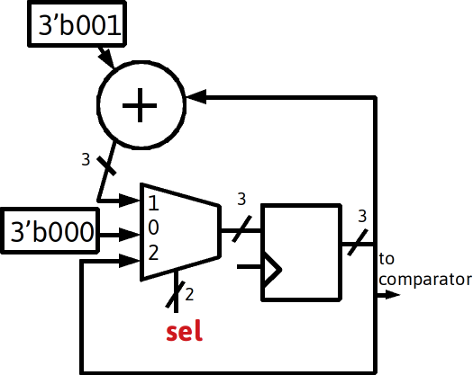
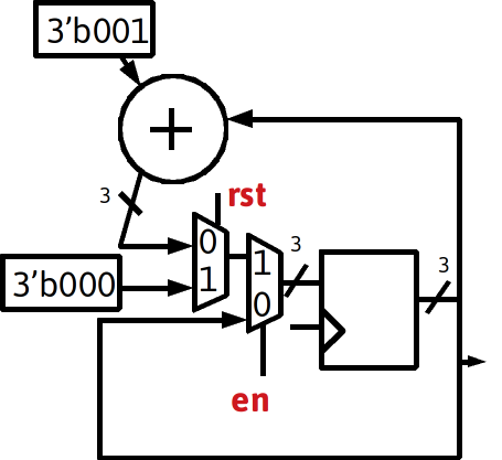
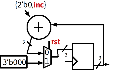
- Note would be the output of the register, the output from the register could be called ( , , , , )
class discussion: timing diagram
always @ (posedge clk) begin
  if (~e_prev & e) e_counter <= e_counter + 1;
  e_prev<=e;
end
which is the same as
always @ (posedge clk)begin
  e_prev<=e;
  if (~e_prev & e) e_counter <= e_counter + 1;
end
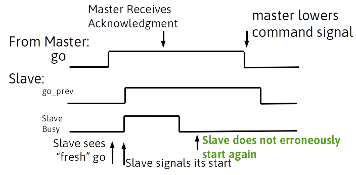
One Reaction per Transition

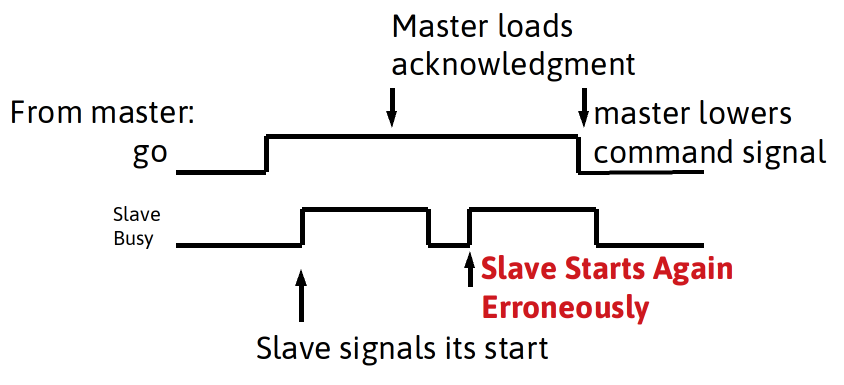
- A slave device commonly starts processes based on a start signal from a master. A slave process may be fast or slow compared to a master. For instance, an instruction processor acting as a master controlling a slave through general I/O ports. Driven by software, it the processor may require many clock cycles to respond (software bit-banging and handshaking can be slow).
- Considering a slow master applying a command signal, yet requiring many clock cycles to respond to a handshaking signal from a slave. The slave might falsely initiate a second round of activity if the command is asserted too long.
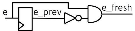
Transition detection for statemachines
-
To alter the behavior, a slave state machine can instead look for a change in the signal in two consecutive clock cycles
-
Saving the previous input value:
always @ (posedge clk) go_prev<=go;
-
using a fresh high as a condition
(go==1 && go_prev==0)
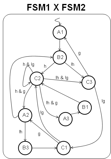
State Machine State Explosion
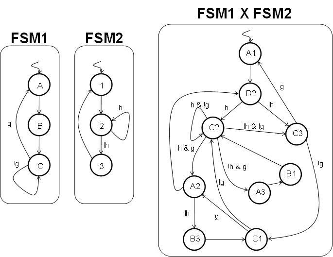
- Consider two state machines. Maybe one captures user input like desired temperature, it has states, inputs and outputs appropriate to perform that task. Perhaps the other controls a heating element based on measured and desired temperature. Separated, they may be fairly simple, but what happens when they are described as a single, flat state machine?
- A multiplicative effect in the number of states. Two three-state FSMs became one nine-state FSM
- This motivates partitioning into multiple state machines in hardware design
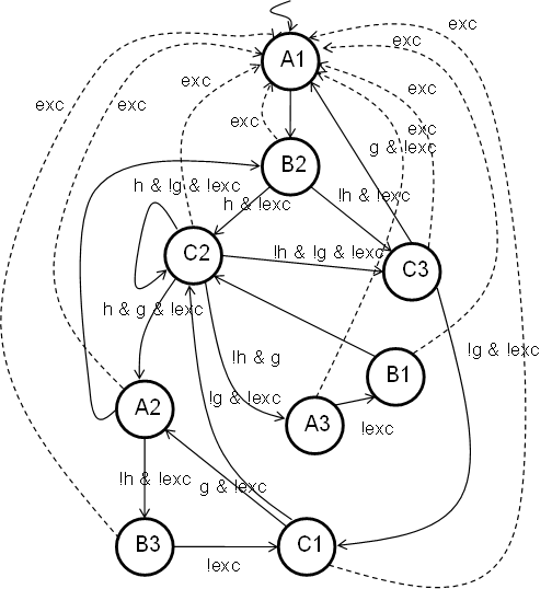
Global Exceptions
- Now, see what happens if a single new condition, a universal exception must be added.
- A dramatic result from only one new condition. Readability and perhaps feasibility of mentally managing the FSM is severely impacted.
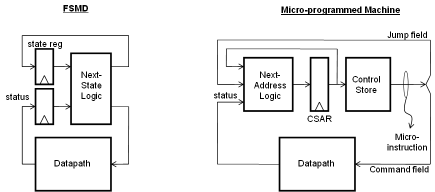
Microprogrammed Control
- Rigid next-state logic is replaced by a rigid next-address logic with a programmable control store.
- Complex designs make require using/creating some form of compiler and a custom language
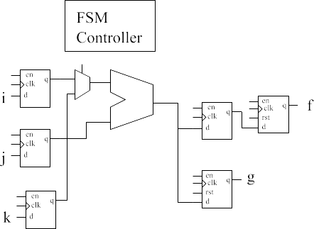
RTL suggested from Code
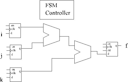
Only datapath connections shown, control and status signals are ommitted
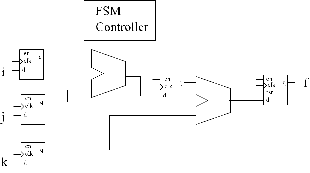
Alternative RTL supporting higher clk rate
Reference Computation Module for discussion
Head
module FSM_opt(
    output reg [7:0] f,
    output reg [7:0] g,
    input clk,
    input wire [7:0] i,
    input wire [7:0] j,
    input wire [7:0] k,
    input rst
    );
reg [7:0] CS;
reg [7:0] i_int,j_int,k_int;

localparam S_0 = 8'b00000000;
localparam S_1 = 8'b00000001;
localparam S_2 = 8'b00000010;
Body
always @ (posedge clk) begin
  if (rst) begin
    CS<=S_0;
    f<=0;
    h<=0;
  end else begin
    case(CS)
      S_0: begin
        i_int<=i;
        j_int<=j;
        k_int<=k;
        CS<=S_1;  end
      S_1: begin
        CS<=S_2;  end
      S_2: begin
        f<=i_int*j_int;
        h<=j_int*k_int;
        CS<=S_0;  end
    endcase
  end
end
endmodule
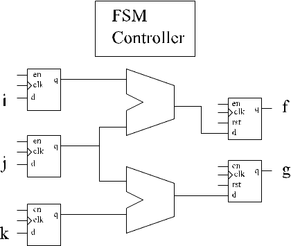
Alternative RTL with lower gate count
always @ (posedge clk) begin
  if (rst) begin
    f<=0; g<=0;
    CS<=S_0;
  end else begin
    case(CS)
      S_0: begin
        i_int<=i;
        j_int<=j;
        k_int<=k;
        CS<=S_1;  end
      S_1: begin

        CS<=S_2;  end
      S_2: begin
        f<=i_int*j_int; //**
        g<=j_int*k_int;
        CS<=S_0;  end
    endcase
  end
end
endmodule
Explicitly coding the rescheduling so that only one multiply is performed per cycle is simple and seen in the next code. However, this doesn’t ensure resource sharing as shown in the figure with one a single multiplier.
Alt. Module Body
always @ (posedge clk) begin
 if (rst) begin
   f<=0; g<=0;
   CS<=S_0;
 end else begin
  case(CS)
   S_0: begin
    i_int<=i;
    j_int<=j;
    k_int<=k;
    CS<=S_1;  end
   S_1: begin
    f_int<=i_int*j_int; //**moved to here**//
    CS<=S_2;  end
   S_2: begin
    f<=f_int;   //*timed output load*//
    g<=k_int*j_int;
    CS<=S_0;  end
  endcase
 end
end
endmodule