https://styleguide.umbc.edu/umbc-colors/

Ch 6 (part II) Microprogrammed Architectures

Ryan Robucci

• Spacebar to advance through slides in order • Shift-Spacebar to go back • Arrow keys for navigation
• ESC/O-Key to see slide overview • ? to see help
Printable Version

References

FSMD vs Microprogram-Controlled Machine

  • With a microprogrammed machine, th next-state logic of FSM is replaced with a programmable memory called the Control Store
  • The control store holds micro-instructions, and is addressed using a registered called a CSAR (Control Store Address Register)

Microprogrammed Control

  • CSAR is the equivalent of a program counter in a microprocessor
  • Next-value of CSAR is determined by next-address logic, using
    1. current value of CSAR
    2. current micro-instruction
    3. value of status flags evaluated by the datapath
  • Default next-state value is (CSAR + 1)
    • In addition, next-address-logic implements conditional and absolute or relative jumps
  • The next-address logic, the CSAR, and the control store implement the equivalent of an instruction-fetch cycle in a microprocessor
  • From the figure, each micro-instruction takes a single clock cycle to execute since there is only one register
  • Within a single clock cycle, the following activities occur:

    1. The CSAR provides an address to the control store which retrieves a micro-instruction
    • micro-instruction has two parts:
      • command-field serves as a command for the datapath
      • jump-field ’points’ to the next-address logic
    1. The datapath executes the command encoded in the micro-instruction, and returns status information to the next- address logic
    2. The next-address logic combines datapath states, micro-instruction jump-field and status returned from the datapath
    • The next-address logic will eventually update the CSAR
    • The critical path of the micro-programmed machine is determined by the delay through the control store, the next-address logic, and the datapath

Addressing Limitations of FSMD

  • While the micro-programmed controller is more complicated than the FSMD, it also addresses the problems of FSMDs very effectively:
    1. complexity
    2. exceptions
    3. control hierarchy
    4. flexibility/reprogrammablity
  • The micro-programmed controller scales well with complexity
    • For example, a 12-bit CSAR will allow a control store with up the 4096 locations, and therefore a micro-program with 4096 steps
    • An equivalent FSM diagram with 4096 states, on the other hand, would be horrible to draw!
  • A micro-programmed machine can deal efficiently with exception handling, since global exceptions are managed directly by the next-address logic
    • For example, the presence of a global exception can feed a hard-coded value into the CSAR, immediately transferring control to an exception-handler
    • Therefore, exception handling does not affect every instruction of a microprogram in the same way as it affects every state of a FSM
  • A micro-programmed machine deals very well with control hierarchies
    • Small modifications to the microprogrammed machine shown above allow pushing and popping of the CSAR for sub-routine calls
  • Micro-programs are flexible and very easy to change after the micro-programmed machine is designed
  • Simply changing the contents of the control store is sufficient to change the program of the machine
  • Here, there is a clear distinction between the architecture of the machine and the functionality implemented using that architecture

Microinstruction Encoding

  • A key design choice is the format of micro-instructions in the control store
  • A sample format for a 32-bit micro-instruction word is shown

Jump Field

  • Of the example 32-bit micro-instruction word, 16 bits are reserved for the datapath and 16 bits are reserved for the next-address logic
  • The next-address field holds an absolute target address, pointing to a location in the control store
    • The address is 12 bit, which allows a control store as large as 4096 locations
  • The next field encodes the operation that will lead to the next value of CSAR
    • As mentioned, the default operation is to increment CSAR
  • For some instructions, the address field is unused
  • Next field allows various jump instructions to be encoded
    • Absolute jumps transfers the value of the address field into CSAR
    • Relative Jumps transfers the value of the address field into CSAR
    • A conditional jump will use the value of a flag to conditionally update the CSAR (or just increment it) it can also use absolute or relative program addressing
  • Dedicating bits to the address field is wasteful
    • In the example, 12 bits are dedicated to the address field
    • Only about 1 in every 5 instructions is a jump
    • There are ways to optimize this so that the address field bits are used for another purpose when the micro-instructions is not a jump instruction

Command Field

  • There are two approaches at micro- instruction encoding
    • Horizontal microcode, where no or minimal decoding is required is done
    • Vertical microcode, where the maximal amount of instruction encoding is done requiring more decoding
  • A wide (horizontal) micro-instruction word allows each control bit of the data path to be stored separately
  • A narrow micro-instruction word, on the other hand, will require the creation of symbolic instructions, which are encoded groups of control-bits for the datapath
    • Therefore, a few bits of the micro-instruction define the value of many control bits in the data-path
  • Here, we create a micro-programmed machine with three instructions on reg a
  • The three instructions do one of the following
    • Double the value in a
    • Decrement the value in a, or
    • Initialize the value in a
  • The datapath shown along the bottom of the figure contains two multiplexers and a programmable adder/subtractor
  • The controller on top shows two possible encodings for the three instructions: a horizontal encoding, and a vertical encoding
  • For horizontal, the control store includes each of the control bits in the datapath directly (3 bits)
  • For vertical, the micro-instructions are encoded with a two-bit micro- instruction word, and a decoder is used
  • So what is the design trade-off between horizontal and vertical microprograms?
  • Vertical micro-programs have a better code density, which is beneficial for the size of the control store.
    • From the figure, the vertically-encoded version of the microprogram will be only 2/3rds of the size of the horizontally-encoded version
  • On the other hand, vertical micro-programs use an additional level of encoding, and need decoding before it can drive the control bits of the datapath
    • Thus, the machine with the vertically encoded micro-program may have a longer critical path
  • In practice, designers use a combination of vertical and horizontal encoding concepts, so that the resulting digital structure is compact yet efficient
  • Consider for example the value of the next field of the micro-instruction word
  • There are six different types of jump instructions, which would imply that a vertical micro-instruction needs no more then three bits to encode these six jumps
  • Yet, four bits have been used, indicating that there is some redundancy
  • The encoding was chosen to simplify the design of the next-address logic
  • Another reason to leave ’room’ in the encoding is to allow future upgrades
  • For example, easy to add an additional conditional jump that uses an arbitrary combination of cf and zf

Microprogrammed Datapath

  • A datapath attached to the microprogrammed controller consists of
    three parts (like the Datapath for the FSMD):
    • Computation units such as adders, multipliers, shifters, and so on.
    • Communications infrastructure (bus, crossbar, point-to-point connection, etc.)
    • Storage, typically a register file or scratchpad RAM
  • Each of these may contribute a few control bits to the micro-instruction word
  • For example,
    • Multi-function computation units have selection bits that determine their specific function,
      Storage units have address bits and read/write command bits
    • Communication busses have source/destination control bits
  • The datapath may also generate condition flags for the micro-programmed controller

Example Datapath Controller

  • Consider the micro-programmed controller with a datapath attached
  • The datapath includes an ALU with shifter unit, a register file
    with 8 entries, an accumulator register, and an input port
  • The micro-instruction word contains 6 fields Nxt and Address are used by the micro-programmed controller while the remaining fields are used by the datapath. The type of encoding is mixed horizontal/vertical.
    • The overall machine uses a horizontal encoding, i.e., each module of the
      machine is controlled independently
    • The sub-modules within the machine use a vertical encoding, e.g., the ALU
      field contains 4 bits and can execute up to 16 different commands

Other characteristics:

  • single instruction per clock cycle
  • ALU operands
    • inputs: accumulator and another from the reg. file or input port
    • output: result sent to the reg file or accumulator
  • datapath operation is controlled by 2 fields, SBUS (to specify source) and Dest (for result)
  • The Shifter generates 2 flags, used by controller to implement conditional jumps
  • A zero-flag: high when the output of the shifter is all-zero
  • A carry-flag: which is defined as the most-significant bit

Writing Microprograms

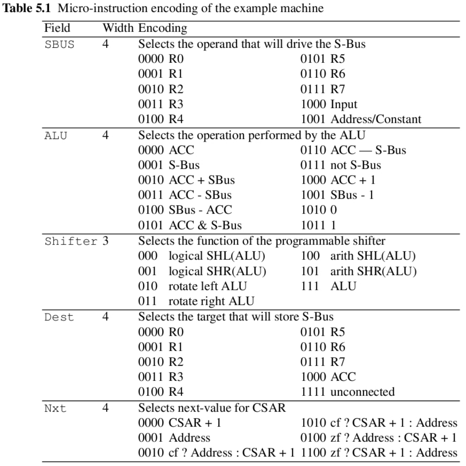
  • table illustrates the encoding used by each module of the design
  • A micro-instruction defines the module function for each module of the micro-programmed machine, including a next-address for the Address field
  • When a field remains unused during a particular instruction, a don’t care value can be specified
  • The don’t care values are designed to prevent unwanted state changes in the datapath
  • For example, an instruction to copy register R2 into the accumulator register ACC would be defined as follows
    • The instruction gets the value in register R2 from the reg file, sends it over the SBus, through the ALU and the shifter, and to the ACC register
  • This functional requirement determines the values in the micro-instruction fields:
    • The SBUS needs to transfer the value of R2, so (from the Table), the SBUS field is set to 0010
    • The ALU needs to pass the SBUS input to the output, therefore, from the Table, the ALU field must be set to 0001
    • The shifter passes the ALU output unmodified, thus the Shifter field is set to 111
    • The output of the shifter is used to update the ACC, so the Dest field equals 1000
    • There is no jump or control transfer for this instruction, so the Nxt field is set to 0000 and the Address field is don’t care
      • The overall micro-instruction is assembled by putting all instruction fields together (as shown below) –0x10F80000

  • Writing a micro-program thus consists of formulating the desired behavior as a sequence of register transfers and then encoding them in the microinstruction fields
  • Higher-level contructs, such as loops and if-then-else statements, are expressed as a sequence of register transfers
  • Although this looks like a tedious task, bear in mind that the programmer has full control over the hardware at every clock cycle
  • Let’s write the micro-program that implements Euclid’s algorithm
    1 ; Command Field           || Jump Field
    2         IN -> R0
    3         IN -> ACC
    4 Lcheck: (R0 - ACC)        || JUMP_IF_Z Ldone
    5         (R0 - ACC) << 1   || JUMP_IF_C LSmall
    6         (R0 - ACC) -> R0  || JUMP Lcheck
    7 Lsmall: (ACC - R0) -> ACC || JUMP Lcheck
    8 Ldone:                       JUMP Ldone
    
    Listing 6.1
  • Lines 2 and 3 read in two values from the input port, and store them into registers R0 and ACC.

  • At the end of the program, the resulting GCD will be available in either ACC or R0

    • The exit condition is implemented in line 4, using a subtraction of two registers and a conditional jump based on the zero-flag
  • When the registers have different values, the program continues to subtract
    the largest one from the smallest one

  • The larger value stored in R0 and ACC is determined by line 5, a conditional
    jump

    • The bigger-than test is implemented using a subtraction, a left-shift and a test on the resulting carry-flag
    • If the carry-flag is set, then the most-significant bit of the subtraction would be one, indicating a negative result in two’s complement
    • This instruction is a conditional jump-if-carry, and is taken if R0 is < then ACC
  • Lines 4, line 5 and line 6 implement an if-then-else stmt using multiple
    conditional and unconditional jump instructions

  • Book gives Example of a Micro-programmed Machine with hardware and microcode
    software in GEZEL
    • The design is itself an example of how the FSMD model can be applied to
      create a more complex micro-programmed machine
  • Next, we show how this can be used to create programming concepts at even higher
    levels of abstraction, using micro-program
    interpreters

Micro-program Interpreters

  • A micro-program is a sequence of commands highly-optimized for a datapath
  • Writing efficient micro-programs for a given machine architecture requires an in-depth understanding of the specific machine architecture and its datapath – this represents some learning overhead over the programmer
  • If a pseudo-assembly language and custom “assembler” are created with the architecture it makes coding coding easier
  • As opposed to implementing complete applications as microcode, common usage of micro-programs is to serve as interpreters for other programs developed at a higher abstraction level, implementing some subset of required features (example: implement multiplier over several clock cycles using adder and shifter)
    • An interpreter is a machine that decodes and executes instruction sequences of an abstract high-level machine -- a macro-machine
  • The instructions from the macro-machine will be implemented as micro-programs
  • A micro-program interpreter is designed as an infinite loop
    • It reads a macro-instruction byte and decodes it into opcode and operand fields
    • It then takes specific actions depending on the values of the opcode

A microprogram Interpreter

  • Consider the following simple machine as a programmers’ model of a macromachine
  • It has four registers RA through RD, and two instructions for adding and multiplying those registers
  • The macro-machine has the same wordlength as the micro-programmed machine but has fewer registers than the micro-programmed machine
  • To implement the macro-machine, we map the macro-register set directly onto the micro-register set (as shown )
  • This leaves register R0 to R3, and the accumulator, available to implement macroinstructions
  • The macro-machine has two instructions: ADD and MUL, which take two source operands (in the macro-machine registers) and generates one
  • The micro-machine needs a decoder for macro-instructions (which are 1 byte wide)
    • The format is two bits for the macro-opcode, and two bits for each of the macroinstruction operands
  • A micro-programmed interpreter can create the illusion of a machine that has more powerful instructions than the original micro-programmed architecture
  • The microprogram itself may require multiple cycles to complete the multiple micro-machine instructions required to implement a single macro-machine instruction, complicating the coding process
  • The concept of micro-program interpreters has been used extensively to design processors with configurable instruction sets, and was originally used to enhance the flexibility of expensive hardware
  • Today, the technique of micro-program interpreter design is still very useful for creating an additional level of abstraction on top of a micro-programmed architecture

Microprogram Pipelineling

  • Pipeline registers can be used to break up the micro-program controller logic
  • However, adding pipeline registers has a large impact on the design of micro-programs
  • Each choice cutes through a different update-loop of the CSAR register
    • through the next-address logic,
    • through the control store and the next-address logic
    • through the control store, the data path, and the next-address logic
  • These combinational paths may limit the maximum clock frequency of the microprogrammed machine
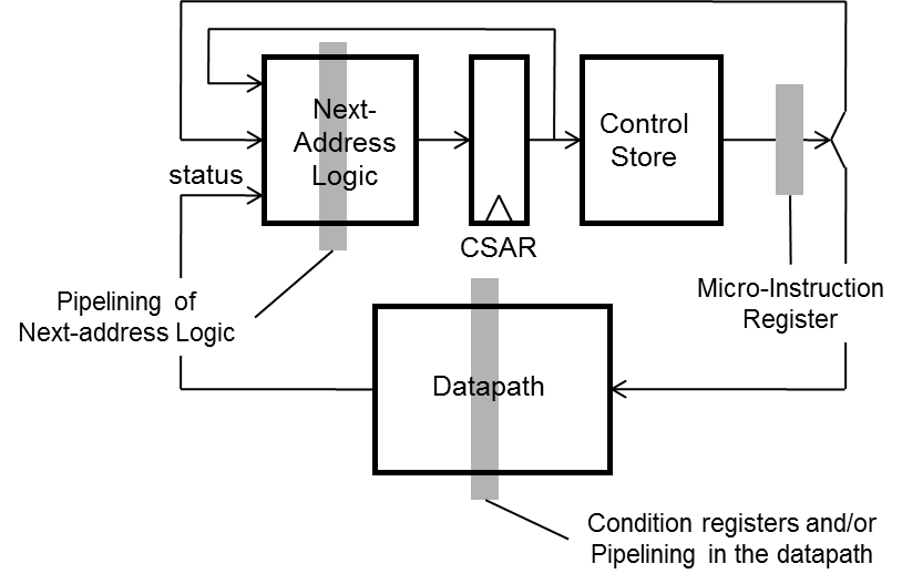
  • There are three common places where pipeline registers may be inserted, as shown above with shaded boxes
  • (i) At the output of the control store as a micro-instruction register: Inserting a register there allows temporal overlap of the datapath evaluation, the next address evaluation, and the micro-instruction fetch
  • (ii) In the datapath to create a datapath pipeline
    • Common to have condition-code registers can be inserted on datapath outputs (status registers)
  • (iii) In the next-address logic: in case high-speed operation is required and the target CSAR address cannot be evaluated within a single clock cycle

(i) Micro-instruction Register

  • Consider the effect of including a micro-instruction register
    • With this register in place, micro-instruction fetch is offset by one cycle from evaluation micro-instruction
  • For example, when the CSAR is fetching instruction i, datapath and nextaddress logic executing instruction i1i-1
  • Consider this offset under the condition that the instruction stream contains a jump instruction
  • The micro-programmer entered a JUMP 10 instruction in CSTORE location 4, and which is fetched in clock cycle N
    • In clock cycle N+1, the micro-instruction will appear at the output of the microinstruction register and its execution will complete in cycle N+2
    • For a JUMP, this means that the CSAR should NOT point to the next instruction in cycle N+2, but the instruction at N+2 has already been fetched
  • To avoid a wasted execution cycle (e.g. no-op after branch) the platform should support
    • delayed execution slot (delayed branch concept) is an instruction that may be executed independent of the branch instruction
      • A compiler may handle this by choosing an appropriate instruction to reorder otherwise the programmer would need to handle this
    • ability to cancel execution of instruction (dependent on branch decision)

(ii) Datapath Condition-Code Register

  • Assume that we have a condition-code register in the datapath, in addition to a microinstruction register
  • The fact that it is a register means that the actual condition code will not be available in the current clock cycle (when the expression is evaluated
  • Therefore, conditional-jump instructions can only operate on datapath conditions from the previous clock cycle
  • Here, the branch instruction in CSTORE(4) is a conditional jump
  • When the condition is true, the jump will be executed with one clock cycle delay
  • The JZ instruction implements the jump in cycle N+2, which tests the condition code generated in cycle N+1 and which becomes available in N+2
  • Here, the micro-programmer just needs to be aware that condition flag must be generated one clock cycle before they are used in conditional jumps
  • Note instruction at N+3 needs to be canceled if jump is taken

(iii) Pipelined Next-Address Logic

  • Assume that there is a third level of pipelining available inside of the next-address update loop
  • For simplicity, we will assume there are two CSAR registers back-to-back in the next-address loop
  • The output of the next-address-logic is fed into the CSAR pipeline register and the output of CSAR pipeline register is connected to CSAR
  • Assuming all registers are initially zero, the two CSAR registers in the next-address loop result in two (independent) address sequences
  • Each instruction of the micro-program is executed twice!
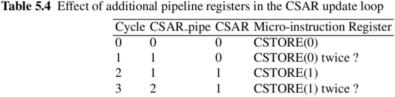
  • careful initialization of CSAR pipe and CSAR needed such that they start out at different values (e.g. 1 and 0)
  • Unfortunately, special load needs to be done for each jump instruction too
  • This complicates the design and the programming of pipelined next-address logic

Complexity for Programmer

  • These examples show that a micro-programmer must be aware of the implementation details of the micro-architecture
  • In particular, he/she MUST be aware of all the delay effects caused by registers
  • This significantly increases the complexity of the development of micro-programs
  • A possible approach is to develop a custom language and/or compiler