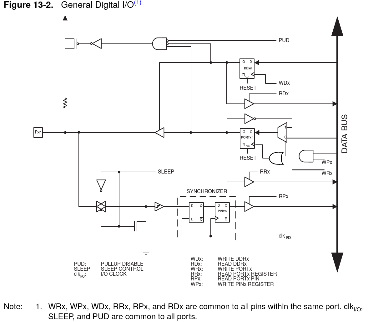
Note the use of a synchronizer in the following datasheet:
ww1.microchip.com/downloads/en/DeviceDoc/doc8018.pdf#page=66
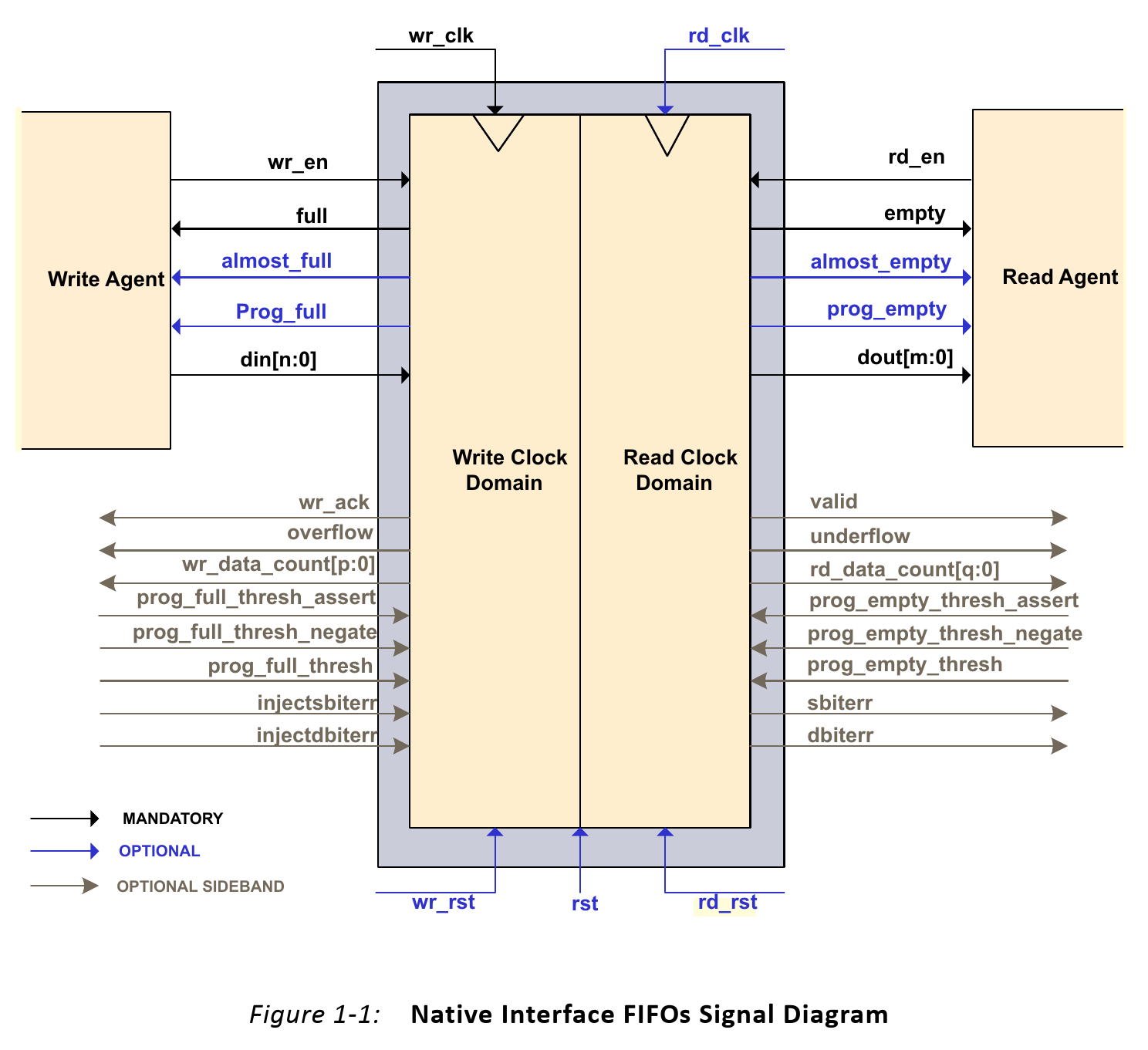
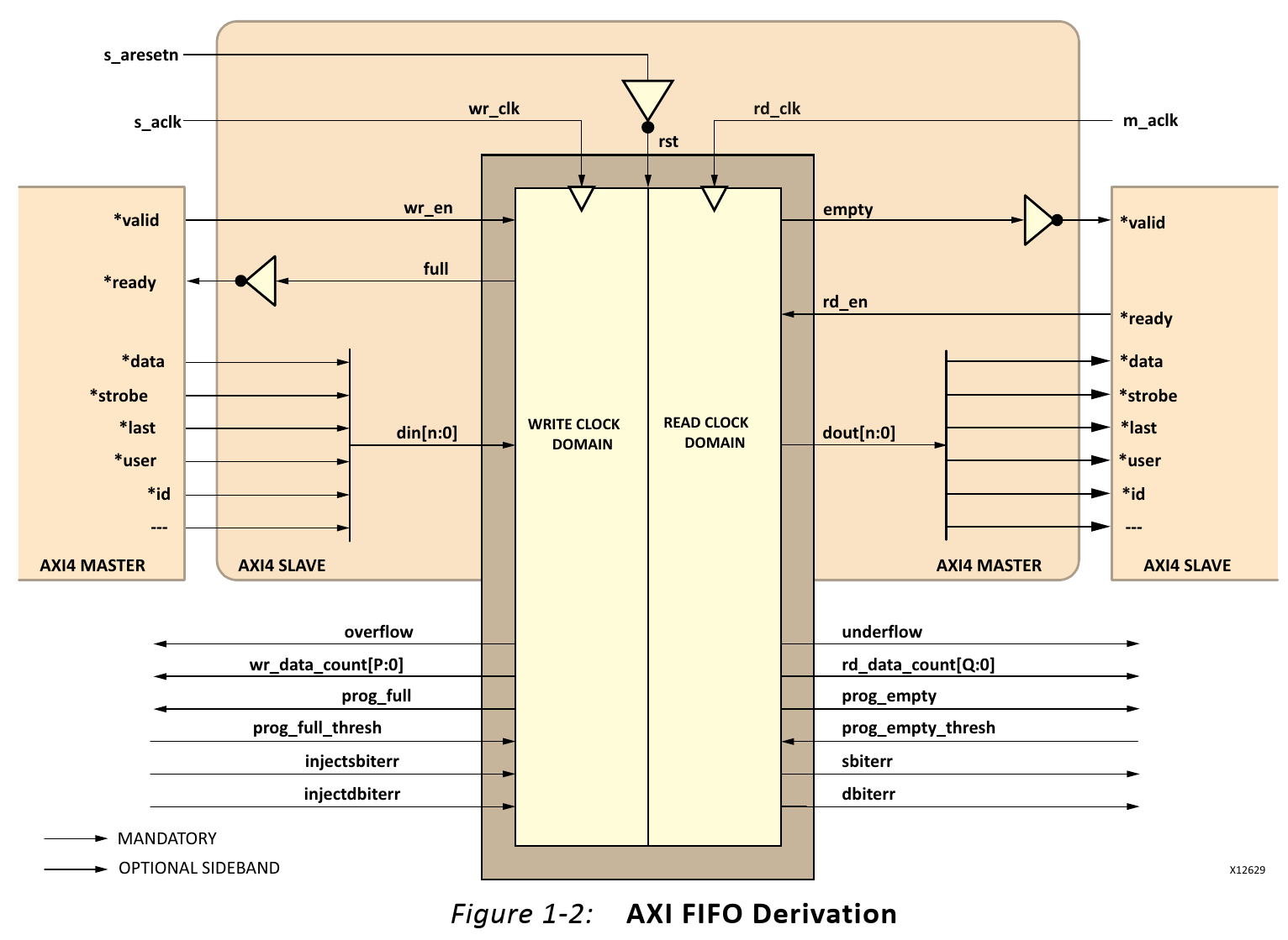
In class overview document and especially page 5 for new material (next slide)
Understanding Metastability in FPGAs ꭝ
While metastability wasn’t as much a concern for a while, modern lowering of supply voltages increased design sizes (with more chains) and increased data rates are cause for concern especially in life-critical applications.
ꭝ Page 5:
FPGA Architecture Enhancements
The metastability time constant C2 in the MTBF equation depends on various factors related to the process technology used to manufacture the device, including the transistor speed and the supply voltage. Faster process technologies and faster transistors allow metastable signals to resolve more quickly. As FPGAs have migrated from 180-nm process geometries to 90 nm, the increase in transistor speed usually improves metastability MTBF. Therefore, metastability has not been a major concern for FPGA designers.
However, as the supply voltage reduces with reduced process geometries, the threshold voltage for the circuit does not decrease proportionally. When a register goes metastable, its voltage is approximately one-half of the supply voltage. With a reduced power supply voltage, the metastable voltage level is closer to the threshold voltage in the circuit. When these voltages get closer together, the gain of the circuit is reduced and the registers take longer to transition out of metastability. As FPGAs enter the 65-nm process geometry and lower, with power supplies at 0.9V and lower, the threshold voltage consideration is becoming more important than the increase in transistor speed. Therefore, metastability MTBFs generally get worse unless the vendor designs the FPGA circuitry to improve metastability robustness.
Altera uses metastability analysis of the FPGA architecture to optimize the circuitry for improved metastability MTBF. Architecture improvements in Altera’s 40-nm Stratix ® IV FPGA architectures and new device development have improved the metastability robustness results by reducing the MTBF C2 constant.
ꭝMetastability in Altera Devices Page 5:
Design Optimizations
Considering a design with little timing slack and poor MTBF, slowing the clock little (200 ps) can have valued impact (fclk=500MHz↔fclk=2000ps)
For a design with a large amount of timing slack, the reduction in MTBF may not be of value
Page 4 discuss MTBF Plot
Brief on Xilinx (discuss “extra” delay”)
ꭝMetastability in Altera Devices Page 5:
Review In-Class:
Synthesis and Scripting Techniques for Designing Multi-
Asynchronous Clock Designs (2001)
http://www.sunburst-design.com/papers/CummingsSNUG2001SJ_AsyncClk.pdf
Details of Code for FIFO implementation shown at end of 2001 paper:
Simulation and Synthesis Techniques for Asynchronous
FIFO Design (2002)
http://www.sunburst-design.com/papers/CummingsSNUG2002SJ_FIFO1.pdf
https://www.glassdoor.com/Interview/uk-digital-design-engineer-interview-questions-SRCH_IL.0,2_IN2_KO3,26.htm
Cisco: Clock domain crossings in cases where very fast sending signals arriving at a much slower clock domain. How to capture without losing any incoming signal event into the slow clock domain? No idea as to how frequent or how long incoming events appear.
Apple Interview Question:
https://www.glassdoor.com/Interview/Describe-how-a-multi-bit-synchronizer-async-fifo-handles-the-variable-delay-of-each-bit-QTN_1243086.htm