FSM I
Ryan Robucci
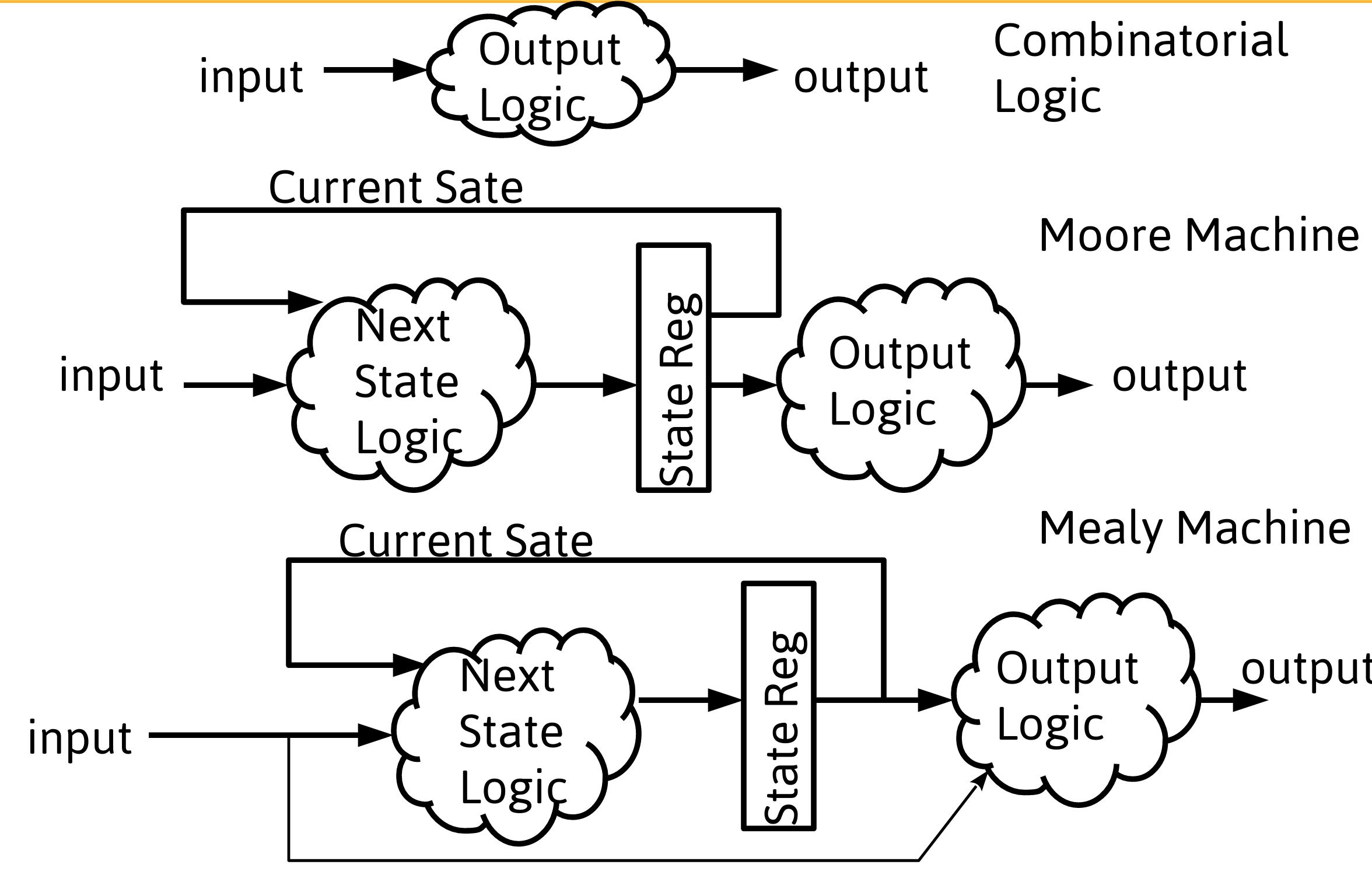
1. State Machines Basics
Mealy Machine

Moore Machine

2. References
- \(\dagger\) A Practical Introduction to Hardware Software Codesign Patrick Shaumont
- \(\dagger\)\(\dagger\) The Verilog® Hardware Description Language,
Donald E. Thomas (Author), Philip R. Moorby (Author)
ISBN:9781402070891
Amazon Link
- Examples for rescheduling
3. Implementation of Mealy and Moore Machines
4. State-Machine Implementation

- All Finite State Machines can be partitioned into a combinatorial and sequential parts
- Often these two pieces are coded in separate code blocks, but they may also be combined sometimes
- Note: some simple register-specific operations such a synchronous reset are coded in either the combination or the sequential blocks, but are often coded in the sequential block to indicate selection of register configuration. An asynchronous clear should be part of the sequential block.
5. State-Machine Verilog Implementation
module FSM (clk, clear, x,y);

input logic clk, clear;
input logic [2:0] x;
output logic [1:0] y;

// Declare the symbolic names for states
          //Verilog: localparam [6:0] S1 = 7'b0000001,S2 = 7'b0000010, S7 = 7'b1000000;
  typedef enum int {S0,S1,S2} state_t;


// Declare current state and next state variables
  //Verilog: reg [2:0] CS,NS;
  state_t CS,NS;


always_ff @ (posedge clk or posedge clear) begin
  if (clear == 1'b1) CS <= S0;
  else CS <= NS;
end

always_comb begin //always @ (CS, x)
  case (CS)
    S0 : begin
         y = 2'b00;
         if (x[2] && ~x[1] && x[0])
           NS = S1;
         else if (x[2] && x[1] && ~x[0])
           NS = S2;
         else
           NS = S0;
    end
    S1 : begin
         y = 2'b10;

    ...
end
6. Mealy Implementation
module FSM (clk, clear, x,y);

input logic clk, clear;
input logic [2:0] x;
output logic [1:0] y;

// States
typedef enum int {S0,S1,S2} state_t;


// Declare current state and next state variables
state_t CS,NS;


always_ff @ (posedge CLOCK or posedge clear) begin
  if (clear == 1'b1) CS <= S1;
  else CS <= NS;
end

always_comb begin //always @ (CS, x)
  case (CS)
    S1 : begin
         y = {x[2] , ~x[1] && x[0]};
         if (x[2] && ~x[1] && x[0])
           NS = S2;
         else if (x[2] && x[1] && ~x[0])
           NS = S4;
         else
           NS = S1;
    end
    S2 : begin
         y = 2'b10;

    ...
- every output bit must be well-defined for every case and input to avoid latches
- for NS, every output bit is set in every case to avoid latches
7. SystemVerilog FSM State Register
Verilog
reg [7:0] CS,NS; //reg!=register
localparam S_init   = 8'b00000000;
localparam S_start0 = 8'b00000001;
localparam S_start1 = 8'b00000010;
SystemVerilog
enum int {S_init, S_start0,S_start1} state_t;
state_t CS,NS;
SystemVerilog enum:
- meaningful enum symbols displayed in waveform viewers and loggers
Symbol accessed as string through member function
name():$strobe("State %s %0d",CS.name(),CS);
- When automatic FSM state reencoding is used, shouldn't put much human effort into providing encodings
- using localparam to provide state encodings requires significant effort and careful use
- later: discuss that with default settings, many synthesizers replace user-provided encodings for FSM states
- therefore use of
enum intseems appropriate when finally using synthesizer-generated encodings
8. "Registered Output Moore" and "Registered Output Mealy" Machines
🛰️ Registered Output FSM
- FSM models generalize sequential circuits
- registered-output logic is common and has advantages and disadvantages to be discussed later
- learn code design patterns/styles for registered-output-logic

- Additionally, code can reuse previous outputs for future output and state updates, meaning the new registers are part of the state of the system
- In code, you can update outputs as needed in a given state and retain values by default if not assigned

- ✏️ Note Formal Size of State Considering any output logic register to be part of the state (serving as "extended state register"), a "Registered Output Mealy" machine is technically a Moore Machine
9. Single Always Block Style for Registered Output Logic (Registered-Output Mealy)
always_ff @ (posedge CLOCK or posedge CLEAR) begin: FSM
  logic _temp;

  if (CLEAR == 1'b1) begin
    CS <= S1;
  end else begin
    case (CS)
      S1 : begin
        _temp = ~x[1];                     //intermediate logic (blocking assignment)
        y  <= {x[2] , _temp & x[0]};       //register intent (non-blocking assignment)
        if (x[2] && _temp && x[0])
          CS <= S2;                        //register intent (non-blocking assignment)
        else if (x[2] && x[1] && ~x[0])
          CS <= S4;
        else
          CS <= S1;
      end
      S2 : begin
          y  <= {x[1] && ~x[1] , x[0]};
         .
         .
         .
- Embedded combination circuit signal assignments ended with blocking assignment and thus encode "immediate" effect. All consumers of blocking assignment results should be within this code block. Even within the block, no consumer should rely on a value assigned from a blocking statement in a previous trigger event.
- Remember, any variable written to inside an edge-triggered block can become a register regardless of the use of blocking or non-blocking…consider every output variable, combinational and sequential, in every case and branch of decision tree and make sure assignments are always made to avoid latches
10. Coding Style for State Machines
🛰️ Registered Output with Three-Always Block Style
- Registered output can cause “cycle delays” so some output transitions need to be coded along with the state transition into a state rather than with the state they are supposed to coincide with (discuss output on prev. slide)
- Sometimes this feels like you’re coding outputs in the “previous state” or coding output ahead of time to account for register delay. I refer to it as coding the output along with the state transition it coincides with. This leads to additional lines of code as you need to code each output logic possibly for every transition to a state rather than once per state
- To avoid this “code bloat”, yet another approach is to code the registered outputs in a separate block. This leads to three blocks:
- Combinatorial Next State Logic along with any combinatorial outputs
- Sequential State Register
- Sequential Registered Outputs according to the destination (next) state from the combinatorial Block.
- Good contrasting examples can be found here: http://www.sunburst-design.com/papers/CummingsSNUG2003SJ_SystemVerilogFSM.pdf
11. Example State-Machine: An Arbitrator
Block Diagram

Example Operation Timing Diagram
- Assume peripherals need a start signal for two-clock cycles
- in the next cycle they present busy as low
- then in the following cycle after they present busy as high and hold it until it coincides with a new result

Statemachine
- Using more states simplifies output logic

always_comb begin
//defaults
startA=0;
startB=0;
...
unique0 case (CS)
  STARTA0: startA=1;
  STARTA1: startA=1;
  STARTB0: startB=1;
  STARTB1: startB=1;
endcase
...
- Using fewer states requires more output logic and, in the code shown effectively embeds extended state information in additional registers

always_ff @ (posedge clk) begin
   if (sel_capture_en) begin
     sel_capture <=sel;
   end
end

always_comb begin
  //defaults
  startA=0;
  startB=0;
  sel_capture_en = 0;
  ...
  unique0 case (CS)
    INIT:   sel_capture_en = 1;
    START0: begin startA=~sel_capture; startB=sel_capture; end
    START1: begin startA=~sel_capture; startB=sel_capture; end
  endcase
  ...
Code (using registered Outputs With Single Always Block)
module control_with_state_machine2(
   input  logic clk,
   input  logic rst,
   output logic startA,     // start signal to   peripheral  A
   output logic startB,     // start signal to   peripheral  B
   input  logic busyA,      // busy  signal from peripheral  A
   input  logic busyB,      // busy  signal from peripheral  B
   output logic ready,      // ready signal to   primary
   input  logic sel0A1B,    // peripheral select
   input  logic start       // go    signal from primary
);

enum int {S_init, S_start0,S_start1} state_t
state_t CS,NS;


always_ff @ (posedge clk) begin
  if (rst == 1)
    CS<=S_init;
  else
    case (CS)
    S_init: begin
      if (start == 1) begin
        startA <= ~sel_0A1B;
        startB <=  sel_0A1B;
        sel_0A1B_saved<= sel_0A1B;
        CS<=S_start0;
      end else begin
        startA <= 0;
        startB <= 0;
        CS<=S_init;
      end
    end
    S_start0: begin
        //startA <= startA;
        //startB <= startB;
       CS<=S_start1;
    end
    S_start1: begin
        startA <= 0;
        startB <= 0;
        CS<=S_wait_for_result;
    end
    S_wait_for_result: begin
       automatic bit [15:0] _result16;
       startA <= 0;
       startB <= 0;
       if (~sel_0A1B_saved && ~busyA || ~sel_0A1B_saved && ~busyB) begin
          startCS<=S_result_H;
          if (~sel_0A1B_saved) begin
             _result16 = resultA;
          end else begin
             _result16 = resultB;
          end
          result <= {result[31:16],_result16}
       end
    end
    S_result_H: begin
       automatic bit [15:0] _result16;
       if (~sel_0A1B_saved) begin
          _result16 = resultA;
       end else begin
          _result16 = resultB;
       end
       result <= {_result16,result[15:0]}
       ready <= 1;
    end
    endcase
end
endmodule
NOTE FSM to tackle Design Complexity
- this is a good point to consider why we build state machines and coding hardware HDL vs software
- a key advantage of a state machine for a logic designer is that the complexity of a large task can be broken down into smaller problems represented by the work done in each state
- unfortunately the hardware designer must be critical of the synthesizer, because the value of hardware itself is in optimization more often than in software which is more often focused on function
- this splits the mind of the designer and makes the overall design task more challenging and time-consuming
- software optimization tools are mature and displace the need for humans to spend time on optimizations, while hardware design tools are maturing
Internal Timing Diagram for FSM
Place holder for in-class timing diagram. Key concepts:
- Identification of implied combinatorial signals including register inputs (outputs and state (NS))
- Arrival of input changes versus response timing
- Coincidence of Code and Output Timing

12. Registered Outputs 3-Always-Block Style
module control_with_state_machine2(
   input  logic clk,
   input  logic rst,
   output logic startA,     //start signal to peripheral A
   output logic startB,     //start signal to peripheral B
   input  logic busyA,      //busy signal from peripheral A
   input  logic busyB,      //busy signal from peripheral B
   output logic ready,      //ready signal to primary
   input  logic sel_0A1B,    //go signal from primary
   input  logic start        //go signal from primary
);

enum int {S_init, S_start0,S_start1} state_t
state_t CS,NS;

assign ready = ~(sel_0A1B?busyB_n:busyA_n); // extra combinational logic outside state machine

  always_ff @ (posedge clk) begin
    if (rst == 1)
      CS<=S_init;
    else
      CS<=NS;
  end

  always_comb begin
     NS = CS;
     case (CS)
    S_init: begin
       if (go) begin
          NS = S_start0;
       end
    end
    S_start0:
      NS = S_start1;
    S_start1:
      NS = S_init;
      endcase
  end

  always_ff @ (posedge clk) begin
     case (NS)
       S_init:
         startA <= 0;
         startB <= 0;
       S_start0:
         startA <= ~selAnB;
         startB <= selAnB;
       S_start1:
         startA <= startA;
         startB <= startB;
      endcase
  end


endmodule
- also need to consider appropriate resets and defaults logic
13. When is registered-output not appropriate?
- Note that the specification outlined in the second following timing diagram could not be satisfied by registered output logic,
- since values are passed through the interface intra-cycle, (within the same cycle, rather than only from one cycle to the next)

14. Review: state variables
- Explicit States are stored in the (primary) state register, but other registers for variables can exist serving as extended state variables
- In-class examples given related to a controller, but more registers will be used later for complex computational machines
- Technically, every register in a digital system is a part of the state. What variables you decide to think of as state in your state diagram and what is coded in the CS register and used in the case statement is up to you.
- When there are many similar states, sometimes combining them in code and adding a register for a variable makes sense. This can reduce the state decoding and state logic and may make the code more maintainable and easier to read. however…
- Testing plans must be considered accordingly.
- More explicitly specified states can be favored for testing plans
15. Review
- FSM Models generalize synchronous sequential logic circuits
- Mealy Machine vs Moore Machine
- Register-Output Logic
- same-cycle/intra-cycle I/O transfer requires combinational logic pathway
- Primary State Register vs Extended State Registers
- Internally embedded state registers and output registers can extend the system state space
- FSM coding in SystemVerilog