Lecture 02 – Verilog
Ryan Robucci
1. References
- \(^\dagger\) Required Textbook for the course: A Practical Introduction to Hardware Software Codesign 1
- Patrick R. Schaumont, A Practical Introduction to Hardware/Software Codesign 2nd Edition, Springer (ISBN:978-1461437369) https://www.springer.com/us/book/978146143736
2. Reading
3. Verilog
- Verilog is event-driven, designed for simulation and adopted as HDL for synthesis
- Should understand how synthesis tools see Verilog, and how simulation tools see Verilog
Must adopt styles with goal to match results
- want same behavior for sim and synth/hardware, prefer no source code differences
- where source differences for simulation and synthesis are necessary, the difference should be minimized

4. Event-Driven Models and Simulation

5. Verilog Execution Model Overview
- A Verilog Simulation involves processing events from different queues that have different priorities
- Most events in the queues can be describe as evaluation or update events
- Evaluation events involve processing or execution. These events can enable other events to enter the active queue, often it enters value assignment events into the queue.
- Update events involve making a value assignment to a variable. These in turn may implicitly enable evaluation events that are sensitive to the changed variable
- continuous assignment:
- expressions are automatically activated when variables change
- assignments are activated by expressions
- use keyword
assign - example:
assign c = a+b;
- procedural assignments:
- blocks of code containing assignments are activated by changes in sensitivity list
- assignments (updates) trigger other continuous assignment expressions or blocks of procedural code
- typical to have many parts of code triggered by a clock signal which is driven (assigned) from a testbench
6. Continuous Assignment Statements (automatically defined trigger and reassignment)
Continuous assignment statements enable (a.k.a. schedule or trigger) an evaluation event when any source element of the RHS expression changes. Upon any expression's resulting value change, an update event for the LHS is added to the active queue.
assign {cout,b} = d+a;- Left-hand-side (LHS) expression:
{cout,b} - Right-hand-side (RHS) expression:
d+a
- Left-hand-side (LHS) expression:
At the start of each simulation, an initial evaluation of continuous assignments occurs at time zero to propagate constant values. The various cascades of dependanceis cause other expresssions and procedural code in the HDL models to be evaluated at time zero as a result. In the the following, an initial evaluation and assignment will occur, but no other update to a will happen in the simulation.
assign a=1;
7. Continuous Assignment in SystemVerilog
- two styles: implicit continous assignment and explicit continous assignment
- Continuous assignment may be described implicitly with wire/real with the wire declaration or provided explicilty later along with an assign keyword
Example Using Wire
...
wire a,b,c,d,e;
...
wire x = a | b; //implicit continous assignment
wire z;
...
assign z = x & (c&d) & e ;  //explicit
in SystemVerilog use logic/reg:
...
logic a,b,c,d,e;
 ...
logic x;
assign x = a | b; //implicit continous assignment
logic z;
...
assign z = x & (c&d) & e ;  //explicit
- Gotcha: initial procedural assignment vs implicit assignment
- because the following uses logic/reg (or if had used real), the following causes a one-time assignment, not a continuous assignment that changes x when a and b change
logic x = a | b; //intial procedural assignment- this could be a gotcha if replacing keyword
wirewithlogic
8. Assignment in Procedural Code
There are two types of assignments that you will see in procedural code
| Operator | Name, Description | Examples |
|---|---|---|
| <= | non blocking assignment statement, schedules assignment but allows next statement to execute | y <= a & b; |
| = | blocking assignment statement, blocks execution of next statement until assignment to left-hand argument (e.g. y) is completed | y = a & b; |
9. Clarification: Sequential and Parallel Blocks
- Sequential procedural blocks are wrapped with begin...end
- Parallel procedural blocks are wrapped with fork...join
- Statement Delay control is relative to entering the block
- Control passes out of the block when the last statement, which may be delayed in time, is completed
- Here is a mix, waiting for two three events before performing assignment
a=b:
begin
   x=y;
   fork
      @event ... ;
      @event ... ;
      @event ... ;
   join
   a = b;
end
- Don't confuse the term sequential code to mean coding a procedural block for sequential hardware
- sequential code refers to control flow of code which defines its functional interpretation, but it can describe the functionality of combinatorial hardware and/or sequential hardware
- sequential hardware would refers to inferred hardware
10. initial and always for procedural code
The initial construct is used to denote code to be executed once at the beginning of the simulation.
The always construct causes code to run repeatedly in an infinite loop. It is only useful with a delay or control construct, otherwise will create a zero delay infinite loop that can block time progression in simulation
This would run infinitely and stall the simulation time:
always x=a&b;
This prints endlessly in the beginning of the simulation:
always begin
  $display(“hello %0t”);
end
0 : hello
0 : hello
0 : hello
0 : hello
0 : hello ...
11. Event Control Operator
- The event control operator may be provided with variables
multiple variables using comma separation. (older syntax is to use or)
@(a,b,c)💀 Old Syntax
@(a or b or c)
Edge selective:
negedgeandposedgerestrict sensitivity to the following transitions@(posedge clk or negedge en)- Negedge Bit Transitions:
- 1→ 0
- 1→ x or z
- x or z → 0
- Posedge Bit Transitions:
- 0 → 1
- x or z →1
- 0 → x or z
Multibit: When posedge and negedge modify a multi-bit operand , only the lsb is used to detect the edge.
1010 -> 0001    posedge


1011 -> 1110    negedge
- Negedge Bit Transitions:
12. Sensitivity List in System Verilog
- was
always @ (a or b or c) begin...end->always @ (a, b,c) begin...endthis syntax is still useful for very selective triggering for modeling no longer required (generally) for RTL (synthesizable code) - for RTL procedural code to describe combinatorial logic commonly became
always @ (*) begin...end- may still use for testbench/non-synthesizable behavioural code
but in SystemVerilog for synthesis use:
always_comb begin ...end
- may still use for testbench/non-synthesizable behavioural code
but in SystemVerilog for synthesis use:
- for procedural code to describe sequential or registered-output combinational logic
in SystemVerilog use:
always_ff @ (posedge clk, posedge reset) begin ...end
- if using block-scoped local variables, provide a blockname is useful
always_ff @ (posedge clk, posedge reset) begin:blockName ...endalways_comb begin:blockName ...end- or for any always block in simulation:
always begin:blockName ...end
13. The stratified event queue
The IEEE standard identifies 5 regions for events to live:
- Active events: in queue ready for execution in current simulation time. The Nondeterminism property states that the order that they are removed is not easily specified nor easily controllable in a complex design. One effect is that concurrent statements and blocks are not guaranteed execution in any order. Furthermore, blocks of behavioral statements may be returned to the active queue at any point even if only partially completed. This allows interleaving of process execution but also unpredictable behavior for concurrent processes with miscoded communication paths between them.
- Inactive events: to be processed at the end of the current simulation time after any active events in the queue. An explicit zero delay (#0) is a way to force an event to be transferred to the inactive event queue.
- Nonblocking assign update events: to be processed at the end of the current simulation time after active and inactive events in the queue. They are processed in the order they are added to the queue.
- Monitor events: to be processed if no active, inactive, or nonblocking assign update events are in the queue. These events do no create any other events. `$monitor` and `$strobe` system tasks generate monitor events.
- Future events: active, inactive and nonblocking assign update events scheduled with a future time
14. IEEE Specification of Event Handling
(Quoted from IEEE Std 1364-2005 with colors added)
while (there are events){
  if (no  active events){
    if      (there are  inactive events){
           activate all inactive events;
    } else if(there are  nonblocking assign update events){
           activate all nonblocking assign update events;
    } else if(there are   monitor events){
           activate all monitor events;
    } else{
          advance T to the next event time;
          activate all inactive events for time T;
    }
  }

  E = any active event;
  if (E is an update event){
    update the modified object;
    add evaluation events for sensitive processes  to event queue;
  }else { /* shall be an evaluation event */
     evaluate the process;
     add update events  to the event queue;
  }
}
15. Order that should shouldn't matter does, but not in proper RTL
Though there could be a well-defined behavior based on the order
module change(input a);
   always @ (a) begin
      $display("%m a:%b",a);
   end
endmodule

module test_order;

   logic a;
   change inst0(a);

   always @ (a) begin: blk0
      $display("%m a:%b",a);
   end

   initial begin
      a=1;
      #1 a=0;
   end

   always @ (a) begin: blk1
      $display("%m a:%b",a);
   end

 change inst1(a);

endmodule
16. Bad Parallel Blocks
Bad Concurrent Assignment (Cummings 2000):
module fbosc1 (y1, y2, clk, rst);
  output y1, y2;
  input clk, rst;
  reg y1, y2;

  always @(posedge clk or posedge rst)
    if (rst) y1 = 0; // reset
    else y1 = y2;

  always @(posedge clk or posedge rst)
    if (rst) y2 = 1; // preset
    else y2 = y1;
endmodule

- This code attempts to model a swap of y1 and y2
- Timing of execution of parallel always blocks is not guaranteed in simulation — though synthesis will probably work since synthesis approaches each always blocks somewhat independently at first
17. Simulation of parallel blocks

18. Good Parallel Blocks
Will not only synthesize correctly, but also simulate correctly:
Good Concurrent Assignment (Cummings 2000):
module fbosc2 (y1, y2, clk, rst);
  output y1, y2;
  input clk, rst;
  reg y1, y2;

  always @(posedge clk or posedge rst)
    if (rst) y1 <= 0; // reset
    else y1 <= y2;

  always @(posedge clk or posedge rst)
    if (rst) y2 <= 1; // preset
    else y2 <= y1;
endmodule

19. Sim Example
module amb_parallel_swap();

  reg clk, rst;
  reg y1, y2;
  reg z1, z2;

 initial clk = 0;
 always #50 clk = ~clk;

 initial begin
  rst = 1;
  #10;
  rst = 0;
 end


  initial begin
   #1000 $finish;
  end
 always @(posedge clk , posedge rst)
  if (rst) y1 = 0; // reset
  else y1 = y2;

always @(posedge clk , posedge rst)
  if (rst) y2 = 1; // preset
  else y2 = y1;
always @(posedge clk , posedge rst)
  if (rst) z1 <= 0; // reset
  else z1 <= z2;

always @(posedge clk , posedge rst)
  if (rst) z2 <= 1; // preset
  else z2 <= z1;
endmodule

20. Blocking and Nonblocking Procedural Assignment with Delays
Blocking assignments cause an immediate evaluation of the right hand side. If delay is provide, then the assignment to the left-hand-expression is scheduled for a future time unless the delay is 0 and in which case the assignment event is entered into the inactive queue. If no delay is specified the statement performs the assignment and returns immediately. Once the assignment is performed, any change will enable any events dependent on the value.
a = #D b+c;delay D before blocking assignment
Nonblocking assignments schedule an evaluation and assignment using the values of the inputs at the time of the scheduling. The event is placed in the nonblocking assignment update event queue for the current time or, if a delay is provided, a future time.
a <= #D b + c;assignment delay D
Delays are only used when modeling for simulation. They should not be used to describe characteristics to a hardware synthesis tool. Typically, all # delays are stripped from code before synthesis.
21. Procedural Blocking and Procedural Assignment Delay
- In the delay before evaluation form (statement delay or evaluation delay), the delay essentially “sleeps” the process until another time before the following code is evaluated.
so call statement delay because delay is essentially before entire statement
#D a = b + c;#D; a = b + c;#D a <= b + c;#D; a <= b + c;
- Assignment delay schedules an assignment for a future time, though the RHS expression evaluation is not delay and may use the variable values at the time of the scheduling rather than the future.
- for delayed blocking assignments, no progression in procedural code until update event is handled (code does not pass control)
- control is not passed out of the block (particularly, always block control triggers may be missed)
- for delayed non-blocking assignments, the update is delayed yet execution control is passed immediately
- for delayed blocking assignments, no progression in procedural code until update event is handled (code does not pass control)
#D a = b + c;
- delay>evaluate>assign>progress
- future values of b,c used
- passes control after assignment
#D a <= b + c;
- delay>evaluate>progress>assign
- future values of b,c used
- passes control after evaluation
Assignment Delay (delay before assignment)
a = #D b + c;
- evaluate>delay>assign>progress
- current values of b,c used
- control passed after blocking assignment
a <= #D b + c;
- evaluate>delay>progress>assign
- current values of b,c used
- control passed after blocking assignment
Code example
 initial #0 $display($time,"  a  b  y  z");

initial begin
    $monitor($time,u8a,u8b,u8y,u8z);
    u8a=0; u8b=0;
    #5;
    #5 u8a = 1;
    #5 u8b = 1;
 end

 always@* begin
    $display($time,u8a,u8b,"       enter nonblocking");
    u8y <= #20 u8a+u8b;
    $display($time,u8a,u8b,"       leave nonblocking");
 end

 always@* begin
    $display($time,u8a,u8b,"       enter blocking");
    u8z = #20 u8a+u8b;
    $display($time,u8a,u8b,"       leave blocking");
 end

 initial #100 $finish;
Result
 Simulator is doing circuit initialization process.
                 0  0  0       enter nonblocking
                 0  0  0       leave nonblocking
                 0  0  0       enter blocking           ***
 Finished circuit initialization process.
                 0  a  b  y  z
                 0  0  0  x  x
                10  1  0       enter nonblocking
                10  1  0       leave nonblocking
                10  1  0  x  x
                15  1  1       enter nonblocking
                15  1  1       leave nonblocking
                15  1  1  x  x
                20  1  1       leave blocking           ***
                20  1  1  0  0
                30  1  1  1  0
                35  1  1  2  0
Stopped at time : 100 ns : File "…/delay_tests.v" Line 56
Delayed Blocking assignment prevented multiple calls.
22. Inertial and Transport Delay
- Transport Delay maintains all transitions and delays them by a specified amount. Models a delay like an ideal transmission line.
- Transport delay does not model pulse rejection described below.
- Inertial Delay also delays transitions, but it only maintains transitions to new states that are held for as long as the specified delay. Approximates models charging and pulse rejection.
- Inertial Delay Pulse Rejection: pulses of a duration less than the specified inertial delay are rejected.

23. Inertial Delay Using Continuous Assignment (wire and SystemVerilog reg/logic)
The following are all examples of inertial delay on a wire.
- delay in the continuous assignment
Verilog/SystemVerilog
wire x_n;
assign #5 x_n = ~n;
wire #5 x_n;
assign x_n = ~n;
wire #5 x_n = ~n;
SystemVerilog
logic x_n;
assign #5 x_n = ~n;
delay in the wire declaration
wire #5 x;
assign x = ~x;
delay in the declaration of a wire with implicit assignment
wire #5 x_n = ~n;⚠️ invalid
logic #5 x_n = ~n;reg #5 x_n = ~n;
- Additive inertial delay: delay in declaration is added to any in the assignment
in this example, the inertial delay to `a` is from `x` is 3:
wire #2 a;
assign #1 a = x;
in this example, the inertial delay to `a` is `4` and for `b` is `3`:
wire #3 a;
wire #2 b;
assign #1 {a,b} = {x,x};
24. Primitive Delay is Inertial Delay
Inertial delay may be provide to primitives using the simplist form of the delay operator.
wire y;
and #3 I1(y,a,b);
In this next example, the inertial delay to y is 4 since delay provide in the declaration is added.
wire #1 y;
and #3 I1(y,a,b);
25. Pulse Rejection is Based on the Result/Output (not input pulse-width)
The pulse rejection behavior is based on the result, not the inputs. The result of an expression to be assigned must maintain a new value for the specified time.
wire y;
assign #2 y = a&b;
wire y;
and #2 I1(y,a,b);

wire y;
assign #3 y = |{a,b,c};
wire y;
or #3 I1(y,a,b,c);

26. Rising and Falling Delay Can Be Different
wire y;
and #(3,2) I1(y,a,b); //#(rising delay,falling delay)
| Transitions | Edge Type |
|---|---|
| 0 → 1, X→1 Z→1 | Rising Edge |
| 1 → 0, X→0, Z→0 | Falling Edge |
Other output edges (e.g. X→Z , 1→Z ) assume the minimum value between the of the rising and falling delays (2 in the example above)
Good Reference:http://verilog.renerta.com/source/vrg00011.htm
Min:Typical:MaxYou can also specify Min:Typ:Max delays which are selected by the simulator:
assign #(1:2:3) y = a & b;
assign #(2:3:4,1:2:3) y = a & b;
Good Reference: http://verilog.renerta.com/source/vrg00025.htm
27. Inertial Delay for "reg"
For a reg, to model inertial delay it is recommend to create a delayed wire copy. Direct modeling of inertial delay is difficult otherwise.
Augmenting reg with Inertial Delay:
wire c;
reg c_nodelay
assign #5 c = c_nodelay;
always @(b,d)
  c_nodelay = ~b|d;
end
28. Modeling of Delay for Sequential Logic
- Study these examples one-by-one as practice to understand Verilog; and reference when trying to model delay (no need to memorize)
- Note that
always_fforalways_combare not used since this a modeling exercise and not for synthesis
parameter TC2Q;
reg q;
always @(posedge clk)
  q <= #TC2Q ~b;
- Evaluate now, assign later
- Models Clk-to-Q delay
❌
parameter TC2Q; reg q; always @(posedge clk) q = #TC2Q ~b;- Evaluate now, assign later
- Bad: Nondeterminism of assignment at later time
❌ (delay the clock)
parameter TC2Q; reg q; always @(posedge clk) #TC2Q q <= ~b;- Evaluate after delay then assign
- Models a delay in the clock signal. Not recommended, better to create and use a delayed clock using other delay methods
❌
parameter TC2Q; reg q; always @(posedge clk) #TC2Q q = ~b;- Evaluate after delay then assign
- Bad: Nondeterminism of assignment at later time
29. Modeling of Transport Delay
- transmission lines
- transport delay models transmission line delay, for which the digital signal at a far destination is a delayed copy of the source end signal
- combinational logic blocks
- inertial delay captures the idea that the "switches" of digital logic must be held in a state for some time to affect the capacitors involve
- useful for modeling switches driving capacitors
- transport delay models a slowed propagation of change through a cascade of gates
- does not represent that an input must be held, only that there is a delay between a change in an input and a resulting in an output
- inertial delay captures the idea that the "switches" of digital logic must be held in a state for some time to affect the capacitors involve
| inertial delay | transport delay |
|---|---|
| - modeling a gate driving a capacitor load at the output of a circuit | - modeling delays through several combinational logic gates, e.g. combinatorial path delay |
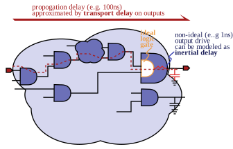
✔️ Trasport Delay for combinational logic
parameter D;
reg y;
always @(a,b)
  y <= #D a&b;
always @(y)
  y_delayed <= #D y;
- Evaluate now, assign later
- Can be use to model transport delay for combinatorial logic or a delayed signal such a from a transmission line
- Note that non-blocking assignment is required to to prevent blocking of re-evaluation
parameter D;
reg y;
always @(a,b)
  y = #D a&b;
- Evaluate now, assign later
- Bad: Blocks reevaluation (ignores input update events)
parameter D;
reg y;
always @(a,b)
  #D y <= a&b;
- Evaluate later and assign
- Bad: Blocks reevaluation
parameter D;
reg y;
always @(a,b)
  #D y = a&b;
- Evaluate later and assign
- Bad: Blocks reevaluation
30. "printing"
display
$display, the "print" statement of Verilog is evaluated and displayed immediately and can be used to observe procedural code as it is evaluated during simulation. The arguments can be variables and plain strings, as well as format strings followed by an appriate number of arguments.
example:
=$display("$display at time=%0d: x_in ='b%b y_out ='b%b", $time, x_in,y_out);=The following example would print 0 followed by 1 with every rising edge of trigger
always @ (posedge trigger) begin
  a=1;
  $display(a);
  a=0;  // no time elapsed since previous assignmnet
  $display(a);
end
strobe
$strobeis like the$displaybut evaluation of arguments and printing is scheduled to occur at the end of the current simulation timethe following code would print 0 followed by 0 with every rising edge of trigger since both of the assignments happen at the same simulation timestep
always @ (posedge trigger) begin
  a=1;
  $strobe(a);
  a=0; // no time elapsed since previous assignmnet
  $strobe(a);
end
strobe is less useful for observing internal behaviour of procedural code, but very useful for montoring resulting values of simulations at each timestep
the following would, with each positive edge of clk, print the resulting value of q twice
always @ (posedge clk) begin
   $strobe(q);  //evalute q at end of timestep
   if (rst) begin
      q<=0;
   else begin
      q<=d;
   end
   $strobe(q);  //evalute q at end of timestep
end
the following would, with each positive edge of clk, print the starting and resulting value of q
always @ (posedge clk) begin
  $display(q);  //print q before assignment
  if (rst) begin
    q<=0;
  end else begin
    q<=d;
  end
  $strobe(q);  //evalute q at end of timestep
end
time
$timeis a useful task which provides the current simulation time as seen in the following example: example:$display("$display at time =%0t: x_in ='b%b y_out ='b%b", $time, x_in,y_out);
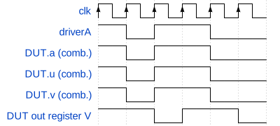
31. Types of Simulation related to RTL code
Timing Simulation (sub-cycle timing)
- a timing simulation with circuit delays displays transitions with sub-cycle timing accuracy

Zero-Delay (zero-time) Simulation, a.k.a. functional/behavioral
- Sometimes called a behavioral / functional simulation since it is checking the digital functionality on a cycle-accurate basis.
32. Delta Cycles and Zero-Time Glitches
- a event-driven simulation advances the time to the next scheduled event
- within that time instant (may be called a time-step), many updates and evaluations may occur through the code
- some nets and variables may be set to multiple values within one timestep
- after multiple updates, the result at the end of a timestep can be the same as before
- this is called a zero-time glitch
- a zero-time glitch can trigger other evaluations with any change
- a VCD file recording may only record results at the end of a given timestep
- may result in downstream signal events where no evidence from upstream signals is recorded
- after multiple updates, the result at the end of a timestep can be the same as before
- advanced simulators may be able to record such events in other database formats and display them at zero-time blips/transistions
VHDL has a more standard concept of a sequence of "sub-time" steps called delta cycles
- delta cycles are a sequences of updates that can be labeled with delta-cycle,
0.05ns+5,and there is an deterministic execution for how a simulator should behave
- with properly written RTL code, zero-time glitches should be irrelevant , but the concept is important for understanding simulation behaviour
- delta cycles are a sequences of updates that can be labeled with delta-cycle,
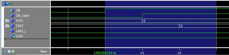
module zero_time_glitch_test;

   logic x;

   always @(posedge x) begin
      $display("x posedge at time",$time);
   end

   initial begin
      x=0;
      #1 x=1;
      x=0;
   end

endmodule
x posedge at time 1
33. SystemVerilog variables: logic/reg
- reg supports continuous assignment through assign keyword
- reg support either a single continous assignment through assign keyword OR assignment in procedural code, not both
- therefor assignment through assign keyword forbids assignment in procedural code
- using logic for declaration is an alternative for reg
- logic becomes functional replacement for nets (e.g. wire) and variables (e.g. reg)
34. Initial assignment of variables
- One-time procedural assignmnet: it is possible to specify an initial value for the register/variable data type through a one-time assignment
reg a = 0; // v2k allows to init variables
reg b, c, d = 0; //just init d
logic a = 0; // v2k allows to init variables
logic b, c, d = 0; //just init d
- synthesis support is inconsistent
35. Implicit and Explicit Port Mapping
consider the following port specification:
module dff2y(  output qA,
               output qB,
               output y,
               input dA,
               input dB,
               input en_n,
               input clk)
- instatiation with explicit port map: uses the port names prefixed with . and allows reordering, no-connect, and omission of ports
dff2y dff2yInstance(
         .dA(alpha),
         .dB(beta),
         .qA(), //qA not used (no-connect)
                //qB omitted  (no-connect)
         .y(s),
         .en_n(~en), //⭐implicit net declaration
         .clk(clk)); //clk
- implicit port map: uses the order of the ports in the definition to imply connections to local nets
dff2y dff2yInstance(
         alpha,beta,  //dff out A B
             unused_0,  //and of qA&qB
         dA,dB,  //dff inputs
          en_n,  //input clk en
           clk   //clk
           );
36. SystemVerilog Variables
regsupports continuous assignment throughassignkeywordregsupport either a single continous assignment throughassignkeyword OR assignment in procedural code, not both- therefor assignment through assign keyword forbids assignment in procedural code
- using
logicfor declaration is an alternative forreg logicbecomes functional replacement for nets (e.g.wire) and variables (e.g.reg)
37. Meta Logic Values
- Verilog Supports more than the two logic values 0/Low and 1/High. The following Metalogic Values are important to be aware of since they may be encountered unintentionally in simulation.
z: high-impedance (not driven)- Verilog supports modeling of bus drivers where multiple potential drivers are connected to one output
- if you see this in simulation, it could mean that you may have neglected to drive a signal
- literals for assignment or use in expressions: using explicit literal size such as
32'bzor shorthand'z - special use: as a wildcard value in RTL; will be discussed later
x: undetermined, can represent the following- result when two drivers don’t agree
- output that cannot be definitely determined to be 1 or 0
- could also represent unintialized memory values in simulation
- literals for assignment or use in expressions: using explicit literal size such as
32'bxor shorthand'x - special use: as a dont care result in RTL; will be discussed later

38. Resolution with undetermined inputs of metalogic values 'x and 'z
Resolving Output with Undetermined Input Value
'xis not always "propagated" if the operation makes the output result unambiguous- (
'zas an input is treated same as'x)
- Unary Resolution
& 2'b1z→ x& 2'b1x→ x& 2'b0z→ 0& 2'b0x→ 0
- Bitwise Resolution
- x&1’b0 → 0 and x|1’b1 → 1
AND resolves input
'xwith input 06'bxxzz0011 & 6'b01010101 → 6'b0x0x0001OR resolves input
'xwith input 16'bxxzz0011 | 6'b01010101 → 6'bx1x10111Complement cannot resolve
 ~4'bxz01
→ 4'bxx10
XOR cannot resolve
  6'bxxzz0011
^ 6'b01010101
→ 6'bxxxx0110
39. Conditional ? Operator and Metalogic
- Syntax:
conditional_expression := selection_expression ? true_expression : false_expression
Can use in both continuous assign statements and procedural blocks
Y=(sel)? A:B;Y = (c>threshold)? A:B;Y=(A>B)? A:B; //max of A and B

? :can be used to represent a mux- (much like can be done with
if elseand two alternative assignments)
- (much like can be done with
Can pass
'zor resolve:'zCAN be propagated from the input through expressions to the output if selection expression is unambiguous 1 or 0Y=(en)?data:16'bz;
en='x gives unknown but
en=1 will pass data and
en=0 will pass multiple z bit
- The conitional operator in a continuous assignment is sometimes THE recommended code for synthesizing a tristate buffer ('z or data)
- Zeros are automatically filled for different length operands
- z in the conditionalexpression is treated like undetermined
'x- If conditionalexpression is ambiguous, both trueex and falseex are evaluated and result is calculated on a
bitwise basis according to truth table below (same as collision of wires, exists since section doesn't matter if both bits are same)
| 1'bx?a:b | a=0 | a=1 | a=x |
|---|---|---|---|
| b=0 | 0 | x | x |
| b=1 | x | 1 | x |
| b=x | x | x | x |
40. Concatenation and Replication Operators
| Operator | Name, Description | Examples |
|---|---|---|
| { , } | Concatenation: concatenation of one, two, or more operands | {4'b1111,4'b0000} {2'b11,2'b11,2'b00,2'b00} Both produce 8'b11110000 |
| {n{x}} | Replication: Allows fixed number of replications (n must be a constant) | assume a=16'hFFFF; then 2{a} produces 32'hFFFFFFFF `2{a}` produces `32'hFFFFFFFF` `{16{1'b0},a}` produces `32'h0000FFFF` <br> `8{2'b10}` produces `16'b1010101010101010` |
- Nesting is allowed
{2b'01,3'b010}→5'b01010{4{2'b01}}→{2'b01,2'b01,2'b01,2'b01}→8'b01010101{4'b0001,{{2'b01},{2'b10}}}→8'b00010110
- No operand should be an unsized literal since the size of the result is not explicit
41. Some additional Data Types
- Integral (integer) types
- 4-State: reg, logic(SystemVerilog), integer
- 2-State: int,shortint,longint,byte,bit
- in theory, use of two state values should facilitate faster simulation
- more fundamentally and noteworthy, they never take on metalogic values
- Signedness:
- Default Signed: byte, shortint, int, integer, and longint default to signed
- Default Unsigned: time, bit, reg, and logic
Signedness can be provdided using keywords signed and unsigned
int unsigned ui;
int signed si;
- Real:
- real is same as C double, also realtime
- shortreal is the same as C float
- Unlike C Real to integer conversion is defined as rounding
- Upon conversion to a real type, z and x are interpretted as zero
- Conversions:
- Recommended to use explicit conversion using casting or system tasks like
$realtobits(see Verilog Manual)
- Recommended to use explicit conversion using casting or system tasks like
42. What is an inferred Latch?
an latch inferred from incomplete specification of a function for a variable (incomplete assignment) ex:
always_comb begin
  if (c>4) begin
    u =a;
  end else if (c>1) begin
    u=b;
    v=b;
  end else begin
    v=a;
  end
end
43. What is an inferred enable?
an inferred register enable from incomplete specification of a function for a variable (incomplete assignment) ex:
always_ff @(posedge clk) begin
  if (c>4) begin
    qu <=a;
  end else if (c>1) begin
    qu<=b;
    qv<=b;
  end else begin
    qv<=a;
  end
end
44. Don't Care Assignment
assignment to literal
xin procedural code- can avoid unintended latches and enables
ex:
always_comb begin
  if (c>4) begin
    u =a;
    v ='x;
  end else if (c>1) begin
    u=b;
    v=b;
  end else begin
    u = 'x;
    v = a;
  end
end
45. Wildcards and Case Statements
- in Verilog
casezis a variant ofcasethat supports wildcard matchingex:
       casez (s) // a 2-bit variable
/*matchA*/        2'b?1:   Q = 1'b1;
/*matchB*/        2'b1?:   Q = 1'b0;
/*default*/     default: Q = 1'bx;
      endcase
- the implication of wildcard matching is that matches specified by different case items may not be unique
- so in the previous example, the actionB is predicated by "!matchA & matchB" rather than "matchB"
a common mistake is the neglect of an input state
casez (s) // a 2-bit variable /*matchA*/ 2'b?1: Q = 1'b1; /*matchB*/ 2'b10: Q = 1'b0; endcase- Full-case: for a case statement, a characteristic that every input state is covered
- avoids inferred latches and enables
- Parallel-case:
- for a case statement, a characteristic of the code that each input case is covered once and only once
- match logic for each case can be independently evaluated
- "matchB" is sufficient for the second item, no need for "!matchA & matchB"
- no "overlap" among matching sets of inputs
46. Complete Assignment
- full case and parallel case are input centric views
- for each output bit, consider if it is assigned in all input cases and what it is assigned
applies to any RTL code with branching logic, not only case
Sample:
always_comb begin
  w = 'x;
  case ({a,b})
     2'1?: y[b]=1; v = 0; w=0;
     2'00: y[0]=1; v = 0; w=1;
     2'01: y[0]=1; v = 0;
  endcase
end
47. System Verilog `priority`, `unique`, `unique0`
Implicitly embedded Sequential State (implied memories from imcomplete assignment)
a.k.a. inferred latch
Incomplete Assignment specification
case(x) // a 2-bit variable
  2'b00: Q = 1'b1;
  2'b11: Q = 1'b0;
endcase
complete:
case (X) // a 2-bit variable
  2'b00:   Q = 1'b1;
  2'b11:   Q = 1'b0;
  default: Q = 1'b0;
endcase
Let synthesizer choose (optimize) by assigning don't care to remaining assignments
case (X) // a 2-bit variable
  2'b00:   Q = 1'b1;
  2'b11:   Q = 1'b0;
  default: Q = 1'bx;
endcase
Overlapping Conditional Cases
by convention, case statements with wild cards should be encoded uniquely
Consider the following:
casez ({a,b,c})
  3'b1??: f = 1'b0;
  3'b??1: f = 1'b1;
endcase
the second case provided does not imply that the output is high whenever c is high.
The following provides parallel case statments: no two match
casez ({a,b,c})
  3'b1??: f = 1'b0;
  3'b0?1: f = 1'b1;
endcase
module dut(f,a,b,c);
  output logic f;
  input a;
  input b;
  input c;

  always_comb begin
    casez ({a,b,c})
    3'b1??: f = 1'b0;
    3'b10?: f = 1'b1;
    3'b??1: f = 1'b1;
    default: f = 1'bx;
  endcase
  end

endmodule
resulting design
SystemVerilog provides `unique case` and `unique0 case` to verify that a design using parallel cases `unique case` enforces matches in all cases while `unique0 case` only enforces uniqueness
a simulator will run through futher cases, but in no particular order, even after the first match to verify unique matches…second match will invoke an warning
casez ({a,b,c})
  3'b1??: f = 1'b0;
  3'b0?1: f = 1'b1;
endcase
Unique Case
- In the code below.
- Line 7: provides full case for every output
- Line 8: with unique/unique0, for each output the decision tree for each output is built with cases considered independently
- Line 12: the default case would not provide a full case, and actually has no effect here although it may be required by linter/coding standards
module dut(int2,int1,int0,irq);

  output reg int2, int1, int0;
   input [2:0] irq;

   always @(irq) begin
      {int2, int1, int0} = 3'b000;
      casez (irq)
        3'b1?? : int2 = 1'b1;
        3'b?1? : int1 = 1'b1;
        3'b??1 : int0 = 1'b1;
        default: {int2, int1, int0} = 3'b000;
      endcase
   end
endmodule // dut
❌
module dut(int2,int1,int0,irq);

  output reg int2, int1, int0;
   input [2:0] irq;

   always @(irq) begin
      {int2, int1, int0} = 3'b000;
      unique casez (irq)
        3'b1?? : int2 = 1'b1;
        3'b?1? : int1 = 1'b1;
        3'b??1 : int0 = 1'b1;
        default: {int2, int1, int0} = 3'b000;
      endcase
   end
endmodule // dut
- Should only use unique-case when properly coding parallel case
- Style recommendation is to always code parallel cases and use `unqiue` to allow tool to identify identify errors
✔️
module dut(int2,int1,int0,irq);

  output reg int2, int1, int0;
   input [2:0] irq;

  always @(irq) begin
    {int2, int1, int0} = 3'b000; //default pre-assigned
    unique casez (irq)
      3'b1?? : int2 = 1'b1;
      3'b01? : int1 = 1'b1;
      3'b001 : int0 = 1'b1;
      default: // {int2, int1, int0} = 3'b000; preassigned
    endcase
   end
endmodule // dut
- clean and explicit full and parallel case
- any variables assigned in one case item must be assigned in all case items, including the default.
module dut(int2,int1,int0,irq);

  output reg int2, int1, int0;
  input [2:0] irq;

  always @(irq) begin
    unique casez (irq)
      3'b1?? : begin int0= 1'b0; int1= 1'b0; int2 = 1'b1; end
      3'b01? : begin int0= 1'b0; int1= 1'b1; int2 = 1'b0; end
      3'b001 : begin int0= 1'b1; int1= 1'b0; int2 = 1'b0; end
      default: {int2, int1, int0} = 3'b000;
    endcase
   end
endmodule // dut
- In the next example, latches are inferred even with the default case provided on line 12.
- using alwayscomb on line 6 should cause the compiler to successfully identify implied memory, but you still need to understand how to identify the cause of implied memory in the code and correct it.
❌
module dut(int2,int1,int0,irq);

  output reg int2, int1, int0;
   input [2:0] irq;

   always @(irq) begin
      //{int2, int1, int0} = 3'b000;
      unique casez (irq)
        3'b1?? : int2 = 1'b1;
        3'b?1? : int1 = 1'b1;
        3'b??1 : int0 = 1'b1;
        default: {int2, int1, int0} = 3'b000;
      endcase
   end
endmodule // dut
48. SystemVerilog case-unique and case-priority
Violations in 2017 Standard (violations not implemented in every tool)
no-match with no provided default overlapping-match affect on synthesis for each case condition affect on simulation additional affect on simulation with no provided default unique violation violation functionality of each case-item determined independently after 1st match continue to look for second match, stopping at violation until violation or match, check all conditions for no-match unique0 violation functionality of each case-item determined independently after 1st match continue to look for second match, stopping at violation priority violation classic cascade condition logic until match, check all conditions for no-match
49. Use of unique0
Important to consider when assigning some outputs and not others in every case
The following is from from: https://dvcon-proceedings.org/wp-content/uploads/systemverilog-2009-enhancements-priority-unique-unique.pdf last few examples
❌ Incorrect Example 1:
unique assertion not satisfied
module dec2_4b (
  output logic [3:0] y,
  input logic [1:0] a,
  input logic en);
  always_comb begin
    y = '0;                 // provids full case
    unique case ({en,a})    // unique assertion
      3'b100 : y[a]='1;
      3'b101 : y[a]='1;
      3'b110 : y[a]='1;
      3'b111 : y[a]='1;
    endcase                // unique assertion not satisfied because of missing cases
    end
endmodule
Example 2:
default satisfies unique assertion's requirement of full case, but is awkward
module dec2_4c (
  output logic [3:0] y,
  input logic [1:0] a,
  input logic en);
  always_comb begin
    y = '0;
    unique case ({en,a})
      3'b100 : y[a]='1;
      3'b101 : y[a]='1;
      3'b110 : y[a]='1;
      3'b111 : y[a]='1;
      default: ; // empty default
    endcase
  end
endmodule
Example 3:
unique0 provides coder's intent to not cover all input cases
  module dec2_4d (
  output logic [3:0] y,
  input logic [1:0] a,
  input logic en);
  always_comb begin
  y = '0;
  unique0 case ({en,a})
    3'b100 : y[a]='1;
    3'b101 : y[a]='1;
    3'b110 : y[a]='1;
    3'b111 : y[a]='1;
  endcase
  end
endmodule
❌ Incorrect Example 4:
- Incorrect attempt to use default to achive complete assignment.
- in example multiple output bits are assigned from the case but not every bit is assigned for every input vector
- provide complete assignment with
always_comb
module dec2_4e (
  output logic [3:0] y,
  input logic [1:0] a,
  input logic en);
  always_comb begin
    unique case ({en,a})
      3'b100 : y[a]='1;
      3'b101 : y[a]='1;
      3'b110 : y[a]='1;
      3'b111 : y[a]='1;
      default: y = '0;
    endcase
  end
endmodule
50. SystemVerilog Set membership case construct: case inside
inside keyword to the right of the paranthesis modifies the matching behavior of case to accept wild-card and ranges
For example:
logic [2:0] status;
always @(posedge clock)
  priority case (status) inside
  1, 3 : task1;         // matches 'b001 and 'b011
  3'b0?0, [4:7]: task2; // matches 'b000 'b010 'b0x0 'b0z0
                        // 'b100 'b101 'b110 'b111
  endcase               // priority case fails all other values including
                        // 'b00x 'b01x 'bxxx
- supports wild-cards in
case_items (literals)- can replace casez in practical use case
- differs from casez in that asymmetric wild-card matching is used, only z in the caseitems are considered, not the input/caseexpression
- supports ranges like [4:7] for 4,5,6,7
module top (q,dA,dB, sel, clk);
  output logic q;
  input logic [1:0] sel;
  input logic dA,dB, clk;

  always_ff @(posedge clk) begin
    unique case (sel) inside
        3 : q<=dB;
    [1:2] : q<=dA;
        0 : q<=q;
    endcase

  end
endmodule
51. priority-if unique-if
- priority keyword provides checks on set of conditions provided in if-else tree for which an else statement is provided
- may use priority when intending to ensure that all cases are covered
- may use unique when intending to code non-overlapping conditions
- may use unique0 when intending to code non-overlapping conditions and ensure all cases are covered
Violations in 2017 Standard (violations not implemented in every tool)
no-match with no else overlapping-match affect on simulation additional affect on simulation with no else unique violation violation after 1st match continue to look for second match, stopping at violation until violation or match, check all conditions for no-match unique0 violation after 1st match continue to look for second match, stopping at violation priority violation until match, check all conditions for no-match
- from IEEE SystemVerilog section 12.4.2 unique-if, unique0-if, and priority-if https://ieeexplore.ieee.org/stamp/stamp.jsp?tp=&arnumber=8299595 :
The keywords unique, unique0, and priority can be used before an if to perform certain violation checks.
If the keywords unique or priority are used, a violation report shall be issued if no condition matches unless there is an explicit else.
Example to invoke violation:
unique if ((a==0) || (a==1)) $display("0 or 1");
else if (a == 2) $display("2");
else if (a == 4) $display("4"); // values 3,5,6,7 cause a violation report
Example Violation-free:
priority if (a[2:1]==0) $display("0 or 1");
else if (a[2] == 0) $display("2 or 3");
else $display("4 to 7"); // covers all other possible values,
                         // so no violation report
If the keyword `unique0` is used, there shall be no violation even when there is no matched. For example:
unique0 if ((a==0) || (a==1)) $display("0 or 1");
else if (a == 2) $display("2");
else if (a == 4) $display("4"); // values 3,5,6,7
                                // cause no violation report
Unique-if and unique0-if assert that there is no overlap in a series of if–else–if conditions, i.e., they are mutually exclusive and hence it is safe for the conditions to be evaluated in parallel.
In unique-if and unique0-if, the conditions may be evaluated and compared in any order. The implementation shall continue the evaluations and comparisons after finding a true condition. A unique-if or unique0-if is violated if more than one condition is found true. The implementation shall issue a violation report and execute the statement associated with the true condition that appears first in the if statement, but not the statements associated with other true conditions.
After finding a uniqueness violation, the implementation is not required to continue evaluating and comparing additional conditions. The implementation is not required to try more than one order of evaluations and comparisons of conditions. The presence of side effects in conditions may cause nondeterministic results.
A priority-if indicates that a series of if–else–if conditions shall be evaluated in the order listed. In the preceding example, if the variable a had a value of 0, it would satisfy both the first and second conditions, requiring priority logic.
52. Appendix
Synthesizer Directives
Some synthesis tools have special directives that can be provided in comments One such directive is to provide full-case not coded explicitly in the standard HDL
Full Case Directive Example:
- Full case directive is redundant if default case is given
- Without the directive, all unmatched cases become latches for SYNTHESIS, and cause holding of values in SIM.
- With the directive, the output defaults to don't care when not covered by the coded cases for the purpose of synthesis avoiding latches.
- This causes a discrepancy between simulation and synthesis unless post-synthesis code is used for simulation
- Using
full_casedirective out of habit when missing a case accidentally in design is poor practice
Parallel Case Directive Example:
This is basically a priority encoder
i.e. case_items 1??,01?,001 for sim
But in synthesis case 2 is handled irrespective of case1 and generates the following
Synthesis Result:

53. Suggested Procedural RTL Coding PracticesRTL Coding Practices
- A) Use non-blocking statements to assign outputs of sequential gates
- B) Use blocking statements to assign outputs of combinatorial gates
- C) Avoid unnecessary latches when coding for FPGAs, but when necessary use non-blocking statements
- Latches fall outside the scope of basic synchronous timing analysis assumptions and complicate timing and functional testing.
- D) Do not make assignments to the same variable from more than one always block
- it confuses synthesizers and can lead to non-deterministic simulation behavior if multiple assignments are made at the same point in time
- E) Consider what each output bit is assigned for any possible evaluation under any input and sequential state condition
- When mixing sequential and combinatorial code, it is easy to get into the mindset of coding for sequential logic outputs (which commonly defaults to retaining previous values in many cases) and overlook what happens with the intermediate combinatorial logic in all cases
- When coding sequential code missed cases can lead to unintended enables, storing and use of old data
- F) Do not use any delay operator for the purpose of affecting synthesis
related guidelines: http://www.sunburst-design.com/papers/
54. Rule: No Continuous Feedback Feedback Feedback Feedback Feedback Feedback Feedback..
- For RTL / synthesizable code, continuous assignments and logic should not have feedback, this would represent combinatorial circuit feedback (which has hysteresis / memory)
- Simulation-only / modeling code emply combinatorial feedback only if delays are added
Review Acceptable ✔️:
- Primitives
logic y,a, b,c; //like wire
...
and (y,a,b,c)
- Continuous assignments
wire y,a, b,c
assign y=a&b&c;
wire y,d0, d1,sel
assign y=sel?d1:d0;
- Feedback ❌
assign y=y&a&b&c;
assign y=a&b;
assign b=y&a;
assign y=(en & x)|(~en & y);
assign y=en?x:y;
nor n1(q,r,q_n);
nor n1(q_n,s,q);
(SR-latch)
assign q=~(r|q_n);
assign q_n=~(s|q);
55. Combinational logic, use always_comb
always_comb:- inferred sensitivity list based on expressions used for reading
- excludes variables declared within block, writtten from within block
- variables assigned shall not be also written from other blocks
- initial trigger for initial evaluation like continuous assign: auto-triggered at time zero after all initial and always blocks
- inferred sensitivity list based on expressions used for reading
for RTL code:
always_comb begin
  a = b & c;
end
for simulation of combinational circuit with propagation delay
always_comb begin
  d <= #1ns b & c;
end
56. Basic Register and use of always_ff
- The sensitivity list includes only a timing control signal, the clock.
logic q; //reg
always_ff @(posedge clk) begin
  q <= d;
end
- Output is only updated on clock edges even if d is changing, this requires memory.
always_ffimposes that- there is only one event control
@ - that assigned variables are not written to by any other process
- tools may also warn if no sequential logic is generated
- there is only one event control
57. Register w/ Synchronous Reset/Clear
- The sensitivity list only includes the clock, indicating that the set and clear only propagate to the output upon the rising clock edge.
- coding templates of some synthesis tools may required that reset signal be handled at the start of the block
- As a general rule, review the synthesis tool's documentation regarding recommended coding templates. Some synthesizers are more flexible then others. Some may for instance require that the reset condition be handled first with an if else construct as shown.
Synchronous reset:
logic q; //reg
always_ff @(posedge clk)
  if(reset) begin
    q <= 0;
  end else begin
    q <= d;
  end
end
Synchronous reset (active low):
logic q; //reg q;
always_ff @(posedge clk) begin
   if(reset_n==1’b0) begin
    q <= 0;
  end else begin
    q <= d;
  end
end
use of advanced clock-control syntax in SystemVerilog:
- cancels blocking triggering from clock when reset is asserted
always_ff @(posedge clock iff reset == 0   or   posedge reset) begin
  $display("this will not print on a rising clock edge when reset is already asserted");
...
end
58. Register w/ Asynchronous Reset/Clear
Active-High Asynchronous Reset
.
logic q; //reg q;
always_ff @(posedge clk, posedge clear) begin
  if(clear) begin
    q <= 0;
  end else begin
    q <= d;
  end
end
- The sensitivity list includes clear signal, indicating the clear should propagate to the output immediately even before any a clock edge.
- the edge specifier for the clear signal is posedge for an active-high asynchronous clear
- The edge specifier in the sensitivity list is required by some synthesizers, though not strictly required for simulation.
Active-Low Asynchronous Reset
- for actively low, changes are triggered on the falling edge of clearn rather than the the rising edge, since a low signal may only be found upon a falling edge
logic q; //reg q;
always_ff @(posedge clk, negedge clear_n ) begin
  if(~clear_n) begin
    q <= 0;
  end else begin
    q <= d;
  end
end
59. Register Synthesis: Resets
- For FPGAS, often asynchronous resets are more efficient than synchronous resets since the inbuilt technology registers often have in-built async. resets, while synchronous resets would involve additional logic like an AND gate in the input data path
- may use when appropriate, such as for system resets, but in this class I recommend using synchronous for learning synchronous digital logic design
always_ff @ (posedge clk, negedge clr_n) //note use of negedge for detecting active-low
  if (clr_n==0)...
  else ...
always_ff @ (posedge clk)
  if (reset_n==0)...
  else...
- For implementation of only a synchronous reset, clear control is disabled if present in available hardware

60. Registered-Output Logic
Combinatorial-only logic includes all inputs as dependancies:
logic y; //reg y;
always_comb //always @(a, b)
  y = a & b;
- Follow the practice of using blocking assignments for all combinatorial logic, avoid using non-blocking
y <= a & b;
Registed Output Logic required sequential output (registered-output combinatorial logic):
logic q;//reg q;
always_ff @(posedge clk) begin
  q <= a & b;
end
logic q;//reg q;
always_ff @(posedge clk) begin
  logic _q;
  _q = 'x;

  _q = a & b;
  q <= q
end
61. Intentional Pipleline for Timing and Throughput

- Can reduce the clock speed – But this slows the entire system
- Can introduce pipelining – Overall propagation of computation is longer (two clock cycles incurring multiple setup and hold times) – Maintains fast system clock
- When timing is satisfied, introducing pipelining in a the critical path of a system can allow an increase the clock rate and therefore overall system throughpu

62. Guideline: Use non-blocking assignment for EVERY output of a register
- It is better to develop the habit of coding all sequential always blocks, even simple single-block modules, using non-blocking assignments
63. new combinatorial always (adoption required)
- use keyword
always_combin combinatorial blocks werealways @ (\*)typically used - inferred sensitivity list
- enforces memoryless logic, tools should check that only combinatorial logic is inferred
Example Use and Error from Quartus (Intel FPGA / Altera)
module top(output logic [3:0] Y, input [3:0\] a,input [3:0] b);
  //logic [3:0] _Y;
    always_comb begin
      //Y = 'Y; //would be a don't care if not commented
      if (a>b) begin
        Y=a;
      end
    end
endmodule
Info (12127): Elaborating entity "top" for the top level hierarchy Warning (10240): Verilog HDL Always Construct warning at top.sv(59): inferring latch(es) for variable "Y", which holds its previous value in one or more paths through the always construct Error (10166): SystemVerilog RTL Coding error at top.sv(59): always_comb construct does not infer purely combinational logic. Info (10041): Inferred latch for "Y[0]" at top.sv(59) Info (10041): Inferred latch for "Y[1]" at top.sv(59) Info (10041): Inferred latch for "Y[2]" at top.sv(59) Info (10041): Inferred latch for "Y[3]" at top.sv(59) Error (12153): Can't elaborate top-level user hierarchy Error: Quartus Prime Analysis & Synthesis was unsuccessful. 2 errors, 2 warnings Error: Peak virtual memory: 409 megabytes Error: Processing ended: Mon Sep 27 14:30:20 2021 Error: Elapsed time: 00:00:09 Error: Total CPU time (on all processors): 00:00:18 Error (293001): Quartus Prime Full Compilation was unsuccessful. 4 errors, 2 warningsOther Example Errors from Quartus
Warning (10230): Verilog HDL assignment warning at xx.sv(49): truncated value with size 32 to match size   of target (8)
Warning (10240): Verilog HDL Always Construct warning at xx.sv(32): inferring latch(es) for variable "_A",   which holds its previous value in one or more paths through the always construct
Warning (10240): Verilog HDL Always Construct warning at xx.sv(32): inferring latch(es) for variable   "_finished", which holds its previous value in one or more paths through the always construct
Warning (10240): Verilog HDL Always Construct warning at xx.sv(32): inferring latch(es) for variable   "_out", which holds its previous value in one or more paths through the always construct
Error (10166): SystemVerilog RTL Coding error at xx.sv(32): always_comb construct does not infer purely   combinational logic.
Example Use
always_comb begin
  _A = 'x;
  case(CS)
    S_INIT: _A = 4;
    S_WAIT: _A = A-1;
  endcase
end
- prevents writing to output variables from other processes in simulation called once at time zero after initial and always procedures
- no blocking timing controls allowed
64. new sequential always (adoption required)
always_ff- output variables should not be written to from any other processing block
- one and only one event control (e.g.
always_ff @(posedge clk or negedge rst_n)), no blocking timing controls allowed
always_latch- like
always_combbut instead software should check if a latch is inferred
- like
65. Enumerated Types (adoption required)
keyword enum
enum logic [1:0] {S_INIT=2'd0, S_WAIT=2'd1, S_FINISH=2'd2} CS,NS; enum logic [1:0] {S_INIT,S_WAIT,S_FINISH} CS,NS;- Useful for State Variables: will display meaning labels in waveform viewers, statemachine viewers
- can print lable with with %s and .name()
- Example to print name and value of current state:
$display( "%s : %d\\n", CS.name, CS );
- Example to print name and value of current state:
66. prefer case-inside construct
- prefer case inside construct over casez (restict use of casex) i.e. 10 should match to caseitem 1z, but input 1z should not match to case item 10
- case inside provide asymmetric wildcard matching often unintended symmetric wildcard matching
- avoid pre-synthesis simulation surprise where z value in select matches wildly
- intend that
10should match tocase_item1z,- but input
1zshould not match tocase_item10
- but input
usual intent:
sel=2'b10
casez (sel)
  2'b10: $display("will match");
  2'b11: $display("would match as well");
  2'b1?: $display("would match as well");
  default: $display("defult");
endcase
sel=2'b10
case (sel) inside
  2'b10: $display("will not match");
  2'b11: $display("will not match");
  2'b1?: $display("will match");
  default: $display("defalt");
endcase
- surprise not good for standard RTL, may not have same result in post-synthesis:
...
  sel=2'b1z
  casez (sel)
    2'b10: $display("will match, not good for standard RTL");
    2'b11: $display("would match as well, not good for standard RTL");
    default: $display("default not reached in pre-syntheis simulation")
  endcase
...
  sel=2'b1z
    case (sel) inside
    2'b10: $display("will not match");
    2'b11: $display("will not match");
    default: $display("default reached in pre-syntheis simulation");
  endcase
- note that
1zwill match to1zand1xwill match to1xwith any type of case matching- use of 2-state types like
bitinstead of 4-state types likelogicmakes such cases moot
- use of 2-state types like
67. Unique and Priority (adoption required)
- case
- with each
casestatement, use one of the following to express design intent when appropriate
- with each
| modifier used with case | violation/warning on existence (formal verification) or encounter (simulation) of | special note |
|---|---|---|
unique |
no-match (no-explicit and no-default) or multiple explicit case item matches |
no-match not supported by all tools |
unique0 |
no-match (no-explicit and no-default) | implemented as unique on some tools |
priority |
no-match | |
none /*priority0*/ |
| modifier used with case | use |
|---|---|
unique |
when providing full-case (considering default when provided) and parallel-case (only considering explicit cases !!! is a default considered redundant?) |
unique0 |
when providing parallel-case in explicit case items; and none of the follwing is appropriate unique |
priority |
when providing full-case (considering default if provided); and none of the follwing is appropriate unique , unique0 |
| none ( /*priority0*/ ) |
none of the follwing is appropriate unique , unique0 , priority |
- this may have some impact on simulation performance, so re-consider use outside of this course
- (not required): with every if-else construct use unique/unique0/priority when appropriate
- A cautious convention:
- use
prioritywith everyif- enforces "full case", which can be satisfied with final else
- promote use
caseinstead ofif-elsewhenuniqueandunique0are appropriate (parallel case intent)
- use
- A less caution convention:
- use
prioritywith almost everyif, except when intent to not cover all cases is clear (code comments are good) - promote use
caseinstead ofif-elsewhenuniqueandunique0are appropriate (parallel case intent)
- use
- A cautious convention:
68. block-local combinatorial-driven logic embedded within edge-triggered block
- in Verilog, variables are static by default
- like C, assignments happen once a and preserve values
- result in common bugs for beginners when coding combinational circuits yet (unaware) depend on memory
- in any procedural code pass, any combinatorial variable that is both set and read in that block must always be assigned a freshly PRODUCED value in that pass before a CONSUMPTION
- to use block-scoped variables, block names are not always required, but consider naming blocks as tools require to provide explicit hierarchical scope names
- local registers:
- best to use block-local static variables for sequential logic registers not used outside the block
- combinatorial logic embedded in edge-triggered block:
- can use block-local variables with
automaticwhen identifying driven signals of combinatorial logic embedded within edge-triggered block - use blocking statements for combinational gate outputs
- embedded comibnatorial logic these are block-local variables (access strictly withing block) that should have "temporary" use, declare using
automatic - prevents "previous" values from being used accidentally
- can use block-local variables with
- Example of
automaticvs
static//*static*/- count number of inputs that are high
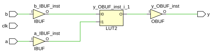
- shown is automatic vs static, each with alwayscomb and always alwaysff (may ignore clk signal is first two examples, exist only to minimize changes) (bit could be logic instead here)
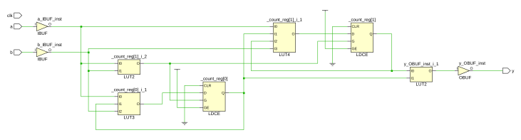
- example has two inputs, and the intent is to count how many of the inputs are high and then output true when both are high
module static_vs_auto (y,a,b,clk);

input bit a,b;
output bit y;
input bit clk;

always_comb begin
  automatic bit [1:0]
            _count = 0;

  if (a) begin
     _count = _count + 1;
  end

  if (b) begin
     _count = _count + 1;
  end

  y <= (_count == 2);

end

endmodule
module static_vs_auto (y,a,b,clk);

input bit a,b;
output bit y;
input bit clk;

always_comb begin
  /*static*/ bit [1:0]
             _count = 0;
             //static is the default

  if (a) begin
     _count = _count + 1;
  end

  if (b) begin
     _count = _count + 1;
  end

  y <= (_count == 2);

end

endmodule
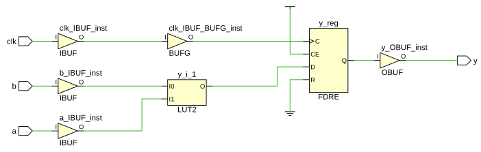
module static_vs_auto (y,a,b,clk);

input bit a,b;
output bit y;
input bit clk;

always_ff @ (posedge clk) begin
  automatic bit [1:0]
            _count = 0;

  if (a) begin
     _count = _count + 1;
  end

  if (b) begin
     _count = _count + 1;
  end

  y <= (_count == 2);

end

endmodule
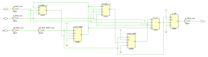
module static_vs_auto (y,a,b,clk);

input bit a,b;
output bit y;
input bit clk;

always_ff @ (posedge clk) begin
  /*static*/ bit [1:0]
             _count = 0; //static is the default

  if (a) begin
     _count = _count + 1;
  end

  if (b) begin
     _count = _count + 1;
  end

  y <= (_count == 2);

end

endmodule
better approaches
- never use static variable initialization
- start with combinatorial erasure, remove if appropriate
module static_vs_auto (y,a,b,clk);

input bit a,b;
output bit y;
input bit clk;

always_ff @ (posedge clk) begin
  bit [1:0] _count; //do not rely on static intialization
  _count = 'x; //ensure combinational

  _count = 0; //happens every process run

  if (a) begin
     _count = _count + 1;
  end

  if (b) begin
     _count = _count + 1;
  end

  y <= (_count == 2);

end

endmodule
69. Separate Compilation (adoption not required)
- new keyword extern
- supports separate compilation like C to "compile" higher-level modules before lower
extern module statemachine(out, finished, skip_to_finish, clk, rst);
Footnotes:
\(^\dagger\) Schaumont